Yaskawa Large Capacity Sigma II Series User Manual
Page 379
8 Inspection, Maintenance, and Troubleshooting
8.2.5 Internal Connection Diagram and Instrument Connection Examples
8-40
8.2.5 Internal Connection Diagram and Instrument Connection Examples
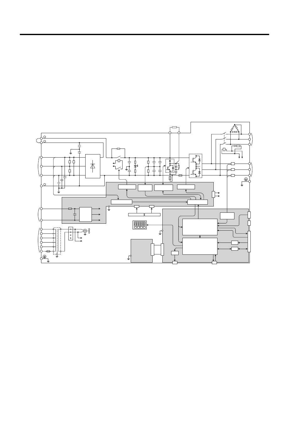
The following diagrams show the SGDH SERVOPACK internal connection and instrument
connection examples. Refer to these diagrams during inspection and maintenance.
Internal Connection Diagram
22 kW or 30 kW for 400 V
Fig. 8.1 SERVOPACK Internal Connection Diagram of 22 kW or 30 kW for 400 V
ASIC
CPU
D/A
A/D
I/O
CN5
CN3
CN10
CN2
CN8
CN1
1PCB
DC/DC
converter
2PCB
+
-
+5V
+24V
+15V
43CN
3PCB
200 VAC
FAN1
215V
1
2
3
4
480V
460V
440V
400V
380V
0
600V 4A
0
E
DC24P
DC24N
DV
DU
DW
MC2
DCCT1
DB24
DBON
W
V
U
W
V
U
DCCT2
DCCT3
DB24
DBON
R
T
S
+
-
+
-
+
-
+
-
TRM1 to TRM6
C1 to C4
TRM4
+
-
+
-
CHARGE
MC1
MC1
R1
200 VAC
C64
C65
C61 ¡ C63
L1/R
DC reactor
connection
terminals
DM1 to DM3
Voltage detection
Panel Operator
Analog monitor
Digital Operator
PG output
Battery
Ground
terminal
Motor
connection
terminals
Dynamic
brake unit
connection
terminals
Reference
pulse input
Sequence I/O
Speed/torque
reference input
PG
(Option Unit)
(PWM control, etc.)
(position/speed
calculation, etc.)
Thermostat 1
Thermostat 2
Voltage
detection
Regenerative
resistor
Regenerative resistor unit
connection terminals
Voltage detection
gate drive
Relay drive
Gate drive
Interface
Main circuit
power supply
input terminals
380 to 480 VAC
Varistor
Varistor
Varistor
(24 VDC)
Control power
supply input
terminals
(380 to 480 VAC)
Control power
supply input
terminals
Ground terminal
1
2
-
L2/S
L3/T
B1
B2
+
+
FU1
FU4
MC2
SA1 to 3
Voltage
detection