Example of i/o signal generation timing, Reference pulse input signal timing – Yaskawa Large Capacity Sigma II Series User Manual
Page 96
4 Parameter Settings and Functions
4.2.2 Position Reference
4-20
The input pulse multiplier function can be used if the reference form is a two-phase pulse
train with a 90
° phase differential. The electronic gear function can also be used to convert
input pulses.
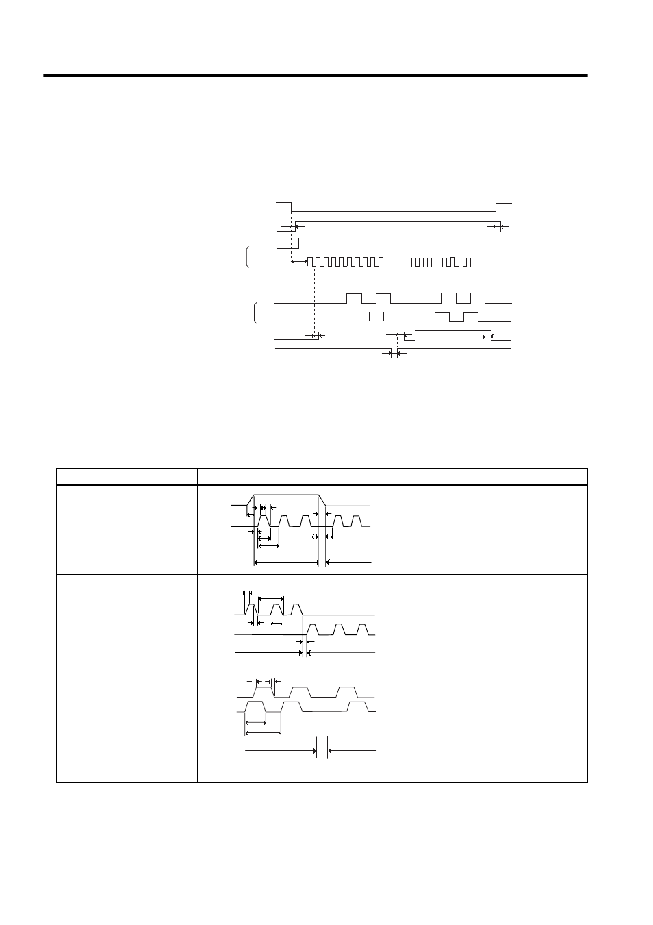
Example of I/O Signal Generation Timing
Note: 1. The interval from the time the servo ON signal is turned ON until a
reference pulse is input must be at least 40 ms. Otherwise the ref-
erence pulse may not be input.
2. The error counter clear signal must be ON for at least 20
µs.
Reference Pulse Input Signal Timing
Servo ON
Baseblock
Sign+pulse
train
Release
t1
≤ 30ms
t2
≤ 6ms
(when parameter
Pn506 is set to 0)
t3
≥ 40ms
PG pulse
t4,t5,t6
≤ 2ms
t7
≥ 20µs
CN1-11
CN1-7
PAO
L
L
L
H
H
H
H
ON
ON
ON
CLR
PBO
t6
t7
t7
t5
t4
t4
t3
t2
t1
/COIN
Reference Pulse Form
Electrical Specifications
Comments
Sign + pulse train input
(SIGN + PULS signal)
Maximum reference frequen-
cy: 500 kpps
(200-kpps open-collector out-
put)
t1, t2
≤ 0.1µs
t3, t7
≤ 0.1µs
t4, t5, t6
> 3µs
τ ≥ 1.0µs
(
τ/T) × 100 ≤ 50 %
Sign (SIGN)
H = Forward refer-
ence
L = Reverse refer-
ence
CW pulse + CCW pulse
Maximum reference frequen-
cy: 500 kpps
(200-kpps open-collector out-
put)
t1, t2
≤ 0.1µs
t3
> 3µs
τ ≥ 1.0µs
(
τ/T) × 100 ≤ 50 %
Two-phase pulse train with
90
° phase differential
(phase A + phase B)
Maximum reference frequency
× 1: 500 kpps
(200-kpps open-collector out-
put)
× 2: 400 kpps
× 4: 200 kpps
t1, t2
≤ 0.1µs
τ ≥ 1.0µs
(
τ/T) × 100 = 50 %
Parameter Pn200.0 is
used to switch the
input pulse multiplier
mode.
Forward
reference
Reverse
reference
t1 t2
t3
t4
t5
t6
t7
T
τ
SIGN
PULS
t2
t3
T
CW
CCW
t1
Forward
reference
Reverse
reference
τ
Phase B leads
phase A by 90
°.
Phase B lags
phase A by 90
°.
B
Phase
A
Phase
t2
τ
T
t1
Reverse
reference
Forward
reference