Dimensional drawings specifications, Mounting base for lrx dimensional drawings – Yaskawa Large Capacity Sigma II Series User Manual
Page 336
7 Servo Selection and Data Sheets
7.5.17 Encoder Signal Converter Unit
7-60
Dimensional Drawings
Specifications
Note: Available from Yaskawa Controls Co., Ltd.
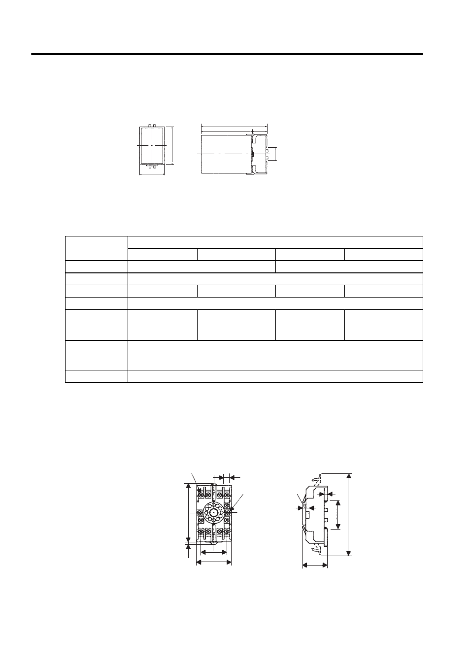
Mounting Base for LRX
Dimensional Drawings
Note: Available from Yaskawa Controls Co., Ltd.
129 (5.08)
100 (3.94)
Units: mm (inches)
80 (3.15)
50 (1.97)
29 (1.14)
35.4
(1.39)
Specifications
Receiver Unit
LRX-01/A1
LRX-01/A2
LRX-01/A3
LRX-01/A4
Power Supply
12 VDC
± 10%, 100 mA
5 VDC
± 5%, 100 mA
Input Signals
Balanced line driver input (RS-422)
Output Signals
Voltage pulse output
Open collector output
Voltage pulse output
Open collector output
Input Signal Level Voltage differential
≥ 0.3 V, internal termination resistance 100 Ω
Output Signal
Level
H: 10 V min. (1 mA)
L: 0.5 V max. (30
mA)
L: 0.5 V max. (30 mA)
Withstand voltage: 50 V
H: 3 V min. (1 mA)
L: 0.5 V max. (30
mA)
L: 0.5 V max. (30 mA)
Withstand voltage: 50 V
Operating Ambi-
ent Temperature
Range
0 to +60
°C
IC Used
AM26LS32C Receiver IC, or equivalent
11-M3.5
×7
Cross slot screw
51 (2.01) max.
33.5 (1.32) max.
4
(0.16)
118 (4.65) max.
35.4 (1.39)
40 (1.57)
±0.2 (0.0079)
2
φ45
(
φ0.18) holes
81 (3.19) max.
Units: mm (inches)
5
(0.20)
4
(0.16)
7.8
(0.31)
4 (0.16)