4 interface circuits – Yaskawa Large Capacity Sigma II Series User Manual
Page 53
2 Basic Operation
2.4.4 Interface Circuits
2-26
Note: 1. Pin numbers in parenthesis () indicate signal grounds.
2. The functions allocated to /TGON, /S-RDY, and /V-CMP (/COIN) output signals can be
changed via parameters. /CLT, /VCT, /BK, /WARN, and /NEAR signals can also be
changed. Refer to 4.3.4 Output Circuit Signal Allocation.
2.4.4 Interface Circuits
This section shows examples of SERVOPACK I/O signal connection to the host controller.
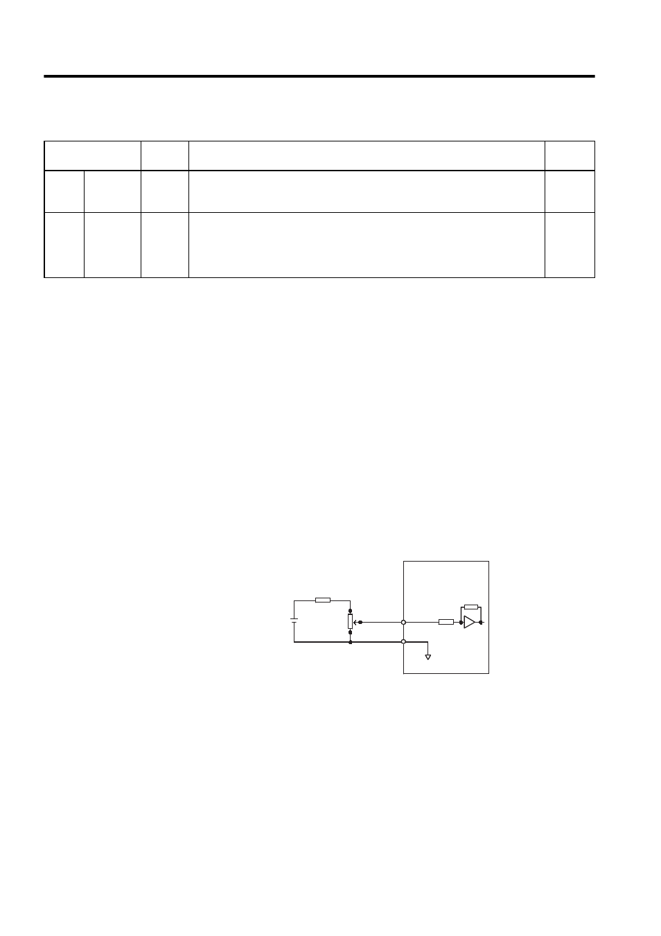
Interface for Reference Input Circuits
Analog Input Circuit
Analog signals are either speed or torque reference signals at the impedance below.
• Reference speed input: About 14 k
Ω
• Reference torque input: About 14 k
Ω
The maximum allowable voltages for input signals is ±12 V.
Posi-
tion
/COIN+
/COIN-
25
26
Positioning completed (output in Position Control Mode): Turns ON when the number
of error pulses reaches the value set. The setting is the number of error pulses set in ref-
erence units (input pulse units defined by the electronic gear).
4.5.3
Not
used.
16
17
23
24
50
These terminals are not used.
Do not connect relays to these terminals.
-
Table 2.4 Output Signal Names and Functions (cont’d)
Signal Name
Pin No.
Functions
Refer-
ence
12V
25HP-10B
2k
Ω
3
1
2
1000: 1
0V
SG
V
T-REF
1.8k
Ω (1/2W) min.
About 14k
Ω
SERVOPACK
-REF or