2 configuration of servo system – Yaskawa Large Capacity Sigma II Series User Manual
Page 19
1.2 Configuration of Servo System
1-5
1
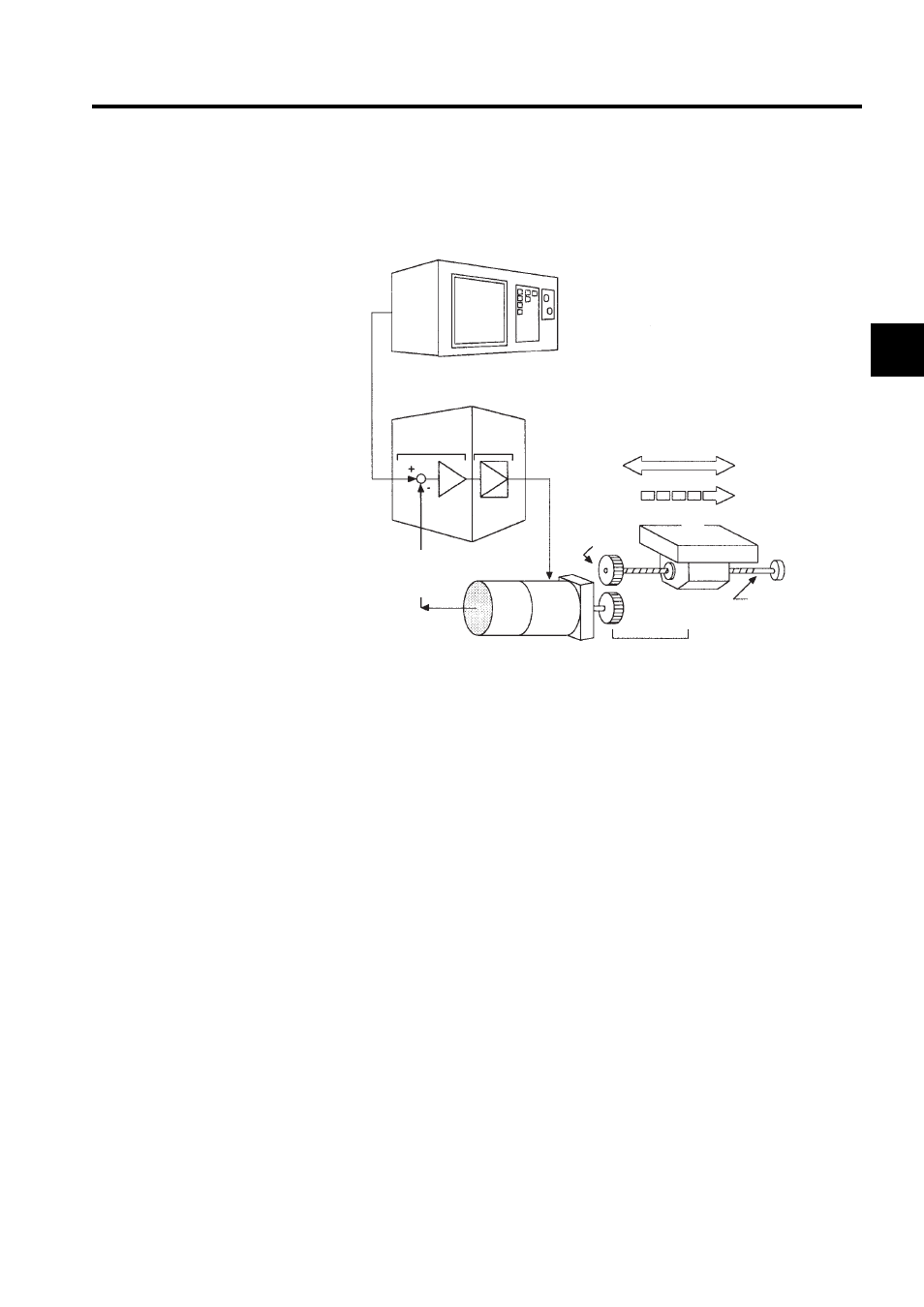
1.2 Configuration of Servo System
The following diagram illustrates a servo system in detail:
Position or
speed
reference
Host controller
Servo amplifier
Comparator Power
amplifier
(Input)
Motor
drive
circuit
(Output)
(5)
(4)
(3)
(2)
(1)
Position
Speed
Gear
Movable table
Controlled
system
Ball screw
Detector servomotor
Drive system
Position or
speed
feedback
(1) Controlled
system:
Mechanical system for which the position or speed is to be controlled. This
includes a drive system that transmits torque from a servomotor.
(2) Servomotor:
A main actuator that moves a controlled system. Two types are available: AC ser-
vomotor and DC servomotor.
(3) Detector:
A position or speed detector. Normally, an encoder mounted on a motor is used as
a position detector.
(4) Servo amplifier:
An amplifier that processes an error signal to correct the difference between a ref-
erence and feedback data and operates the servomotor accordingly. A servo
amplifier consists of a comparator, which processes error signals, and a power
amplifier, which operates the servomotor.
(5) Host controller:
A device that controls a servo amplifier by specifying a position or speed as a set
point.