Alignment, Wiring the servomotor power lines, Wiring the servomotor thermostat – Yaskawa Large Capacity Sigma II Series User Manual
Page 35: Wiring the servomotor fan
2 Basic Operation
2.2.2 Installing the Servomotor
2-8
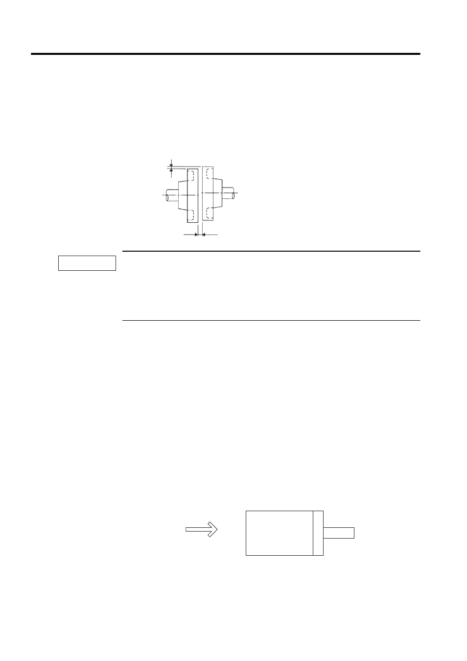
Alignment
Align the shaft of the servomotor with that of the equipment to be controlled, then connect
the shafts with flexible couplings. Install the servomotor so that alignment accuracy falls
within the following range.
1. Vibration that will damage the bearings will occur if the shafts are not properly aligned.
2. Do not allow direct impact to be applied to the shafts when installing the coupling. Otherwise the
encoder mounted on the opposite end of the shaft may be damaged.
3. Before mounting the pinion gear directly to the motor output shaft, consult your Yaskawa sales rep-
resentative.
Wiring the Servomotor Power Lines
Connect the servomotor power lines (U, V, and W) to the servomotor terminal block (M10)
in the servomotor terminal box. Connect the ground wire to the ground screw in the terminal
box.
Wiring the Servomotor Thermostat
The servomotor has a built-in thermostat. Wire the thermostat leads (l, lb) to the terminal
block (M4) in the servomotor’s terminal box.
Wiring the Servomotor Fan
Wire the servomotor fan leads U(A), V(B), and W(C) so that the direction of air flows
according to the following diagram. If the air flows in the opposite direction, change the wir-
ing of any of the two phases U, V, and W.
Measure this distance at four different positions in the circumference.
The difference between the maximum and minimum measurements
must be 0.03 mm or less. (Turn together with couplings)
Measure this distance at four different positions in the
circumference. The difference between the maximum
and minimum measurementsmust be 0.03 mm or less.
(Turn together with couplings)
IMPORTANT
Servomotor
Direction of
cool air