7 using the warning output signal – Yaskawa Large Capacity Sigma II Series User Manual
Page 154
4 Parameter Settings and Functions
4.5.7 Using the Warning Output Signal
4-78
This signal indicates the SERVOPACK received the Servo ON signal and completed all
preparations.
The following parameter setting is used to change the CN1 connector terminal that outputs
the /S-RDY signal.
The parameter is factory set so the /V-CMP signal is output between CN1-29 and -30. See
4.3.4 Output Circuit Signal Allocation for more details on parameter Pn50E.
4.5.7 Using the Warning Output Signal
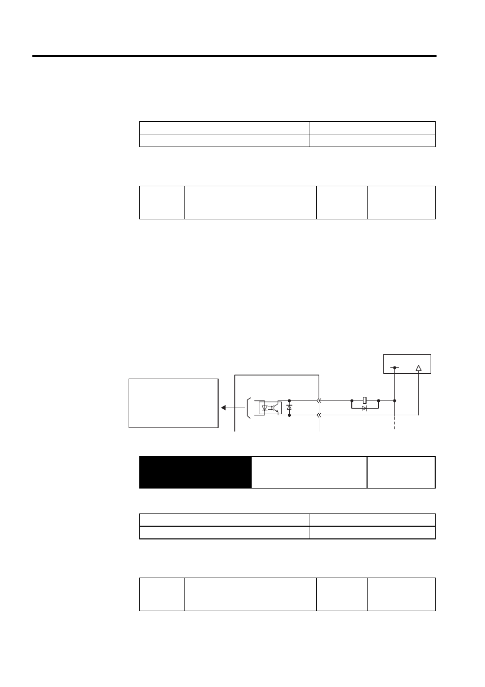
The basic use and wiring procedure for the warning (/WARN) output signal (photocoupler
output signal) are given below.
The signal consists of the following two output signals.
/WARN signals: Overload and regenerative overload
Note: Parameter Pn50F.3 is used to allocate output terminals for *1 and *2.
This output signal indicates an overload or regenerative overload warning.
The following parameter setting is used to change the CN1 connector terminal that outputs
the /WARN signal.
ON:
Closed or low level
Servo is ready.
OFF:
Open or high level
Servo is not ready.
Pn50E
Output Signal Selections 1
Factory
Setting:
3211
Speed/Torque
Control,
Position Control
Output
→ /WARN
Warning Output Signal
Speed/Torque
Control,
Position Control
OFF:
Open or high level
Normal operation.
ON:
Closed or low level
Error warning status
Pn50F
Output Signal Selections 2
Factory
Setting:
0000
Speed/Torque
Control,
Position Control
SERVOPACK
Photocoupler output
(per output)
Maximum operating voltage:
30 VDC
Maximum output current:
50 mA DC
I/O power supply
CN1-∗1
CN1-∗2
/WARN+
/WARN-
+24 V
0V