Selecting mode switch setting – Yaskawa Large Capacity Sigma II Series User Manual
Page 194
5.2 High-speed Positioning
5-11
5
Selecting Mode Switch Setting
The SERVOPACK incorporates four mode switch settings (0 to 3). Select a mode switch
with the following parameter (Pn10B.0).
Torque Reference Input Used as Detection Point (Standard Setting)
With this setting, if the value of torque reference input exceeds the torque set in parameter
Pn10C, the speed loop switches to P control.
The SERVOPACK is factory-set to this standard mode. (Pn10C = 200)
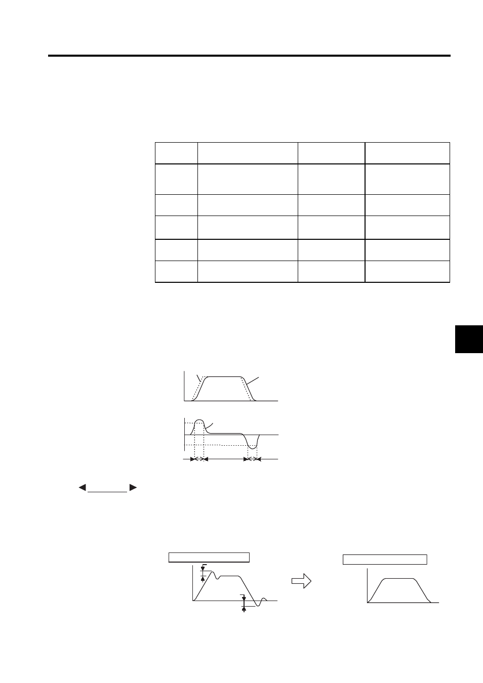
Operating Example
If the system is always in PI control without using the mode switch function, the speed
of the motor may overshoot or undershoot due to torque saturation at the time of the
acceleration or deceleration of the motor. The mode switch function suppresses torque
saturation and eliminates the overshooting or undershooting of the speed of the motor.
Pn10B.0
Setting
Selecting Mode Switch Set-
ting
Parameter to Set
Detective Point
Set Unit
0
Uses torque reference as the
detection point. (Standard set-
ting)
Pn10C
Percentage of rated
torque: %
1
Uses speed reference input as
the detection point.
Pn10D
Motor speed: min
-1
2
Uses acceleration as the detec-
tion point.
Pn10E
Motor acceleration:10
min
-1
/s
3
Uses error pulse input as the
detection point.
Pn10F
Reference units
4
Mode switch function is not
used.
-
-
Motor speed
Reference speed
Speed
Internal torque reference
+Pn10C
Torque 0
- Pn10C
PI control
PI control
PI control
P control
P control
EXAMPLE
Overshooting
Under-
shooting
Motor
speed
Time
Without mode switch
With mode switch
Motor
speed
Time