Selecting a reference pulse form, Important, Example – Yaskawa Large Capacity Sigma II Series User Manual
Page 94
4 Parameter Settings and Functions
4.2.2 Position Reference
4-18
• When Vcc is +12 V: R1 = 1 k
Ω
• When Vcc is +5 V: R1 = 180
Ω
Note: The following table shows the signal logic for an open-collector out-
put.
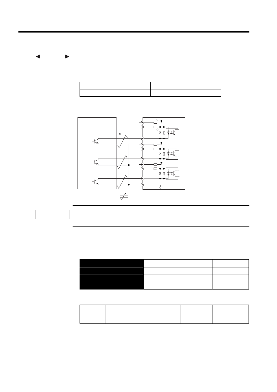
This circuit uses the 12-V power supply built into the SERVOPACK. Input is not insulated.
The noise margin of the input signal will decrease if the reference pulse is given using an open-collec-
tor output. Set parameter Pn200.3 to 1 if the position drifts due to noise.
Selecting a Reference Pulse Form
Use the following parameters to select the reference pulse form used.
The servomotor only rotates at an angle proportional to the input pulse.
When Tr1 is ON
Equivalent to high-level input
When Tr1 is OFF
Equivalent to low-level input
→ Input PULS CN1-7
Reference Pulse Input
Position Control
→ Input /PULS CN1-8
Reference Pulse Input
Position Control
→ Input SIGN CN1-11
Reference Sign Input
Position Control
→ Input /SIGN CN1-12
Reference Sign Input
Position Control
Pn200.0
Reference Pulse Form
Factory
Setting:
0
Position Control
EXAMPLE
Approx.
9 mA
ON: 1.5 V max.
: represents twisted-pair wire.
SERVOPACK
Host controller
CN1-11
CLR
/CLR
SIGN
PULS
CN1-15
CN1-18
+12V
1 k
150
CN1-7
CN1-3
CN1-8
/PULS
PL1
Tr 1
CN1-13
CN1-12
/SIGN
PL2
CN1-14
PL3
CN1-1
Photocoupler
IMPORTANT