Ground fault current protection, Phase loss trip delay – Rockwell Automation 592- E300 Overload Relay User Manual User Manual
Page 89
Rockwell Automation Publication 193-UM015B-EN-P - June 2014
89
Protective Trip and Warning Functions Chapter 5
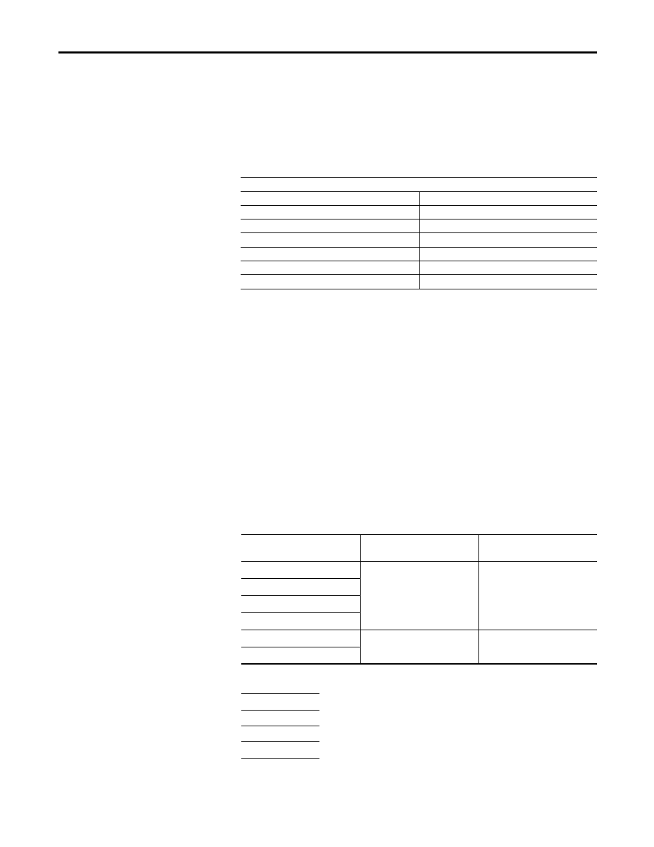
Phase Loss Trip Delay
Phase Loss Trip Delay (Parameter 240) allows the user to define the time period
for which a phase loss condition must be present before a trip occurs. It is
adjustable from 0.1…25.0 seconds.
Table 68 - Phase Loss Trip Delay (Parameter 240)
Ground Fault Current Protection
In isolated or high impedance-grounded systems, core-balanced current sensors
are typically used to detect low level ground faults caused by insulation
breakdowns or entry of foreign objects. Detection of such ground faults can be
used to interrupt the system to prevent further damage or to alert the appropriate
personnel to perform timely maintenance.
The E300 Electronic Overload Relay provides core-balanced ground fault
current detection capability, with the option of enabling Ground Fault Trip,
Ground Fault Warning, or both. The ground fault detection method and range
depends upon the catalog number of the E300 Sensing Module and Control
Module ordered.
Table 69 - Ground Fault Capabilities
➊ One of the following Catalog Number 193-CBCT_ Core Balance Ground Fault Sensors must be used:
Phase Loss Trip Delay (Parameter 240)
Default Value
1.0
Minimum Value
0.1
Maximum Value
25.0
Parameter Type
USINT
Size (Bytes)
1
Scaling Factor
10
Units
Sec
Catalog Number
Ground Fault Method
Ground Fault Trip/Warning
Range
193-ESM-IG-__-__
Internal
0.5…5.0 A
592-ESM-IG-__-__
193-ESM-VIG-__-__
592-ESM-VIG-__-__
193-EIOGP-22-___
External
➊
0.02…5.0 A
193-EIOGP-42-___
1 — Ø 20 mm window
2 — Ø 40 mm window
3 — Ø 65 mm window
4 — Ø 85 mm window