Rockwell Automation 592- E300 Overload Relay User Manual User Manual
Page 45
Rockwell Automation Publication 193-UM015B-EN-P - June 2014
45
Installation and Wiring Chapter 2
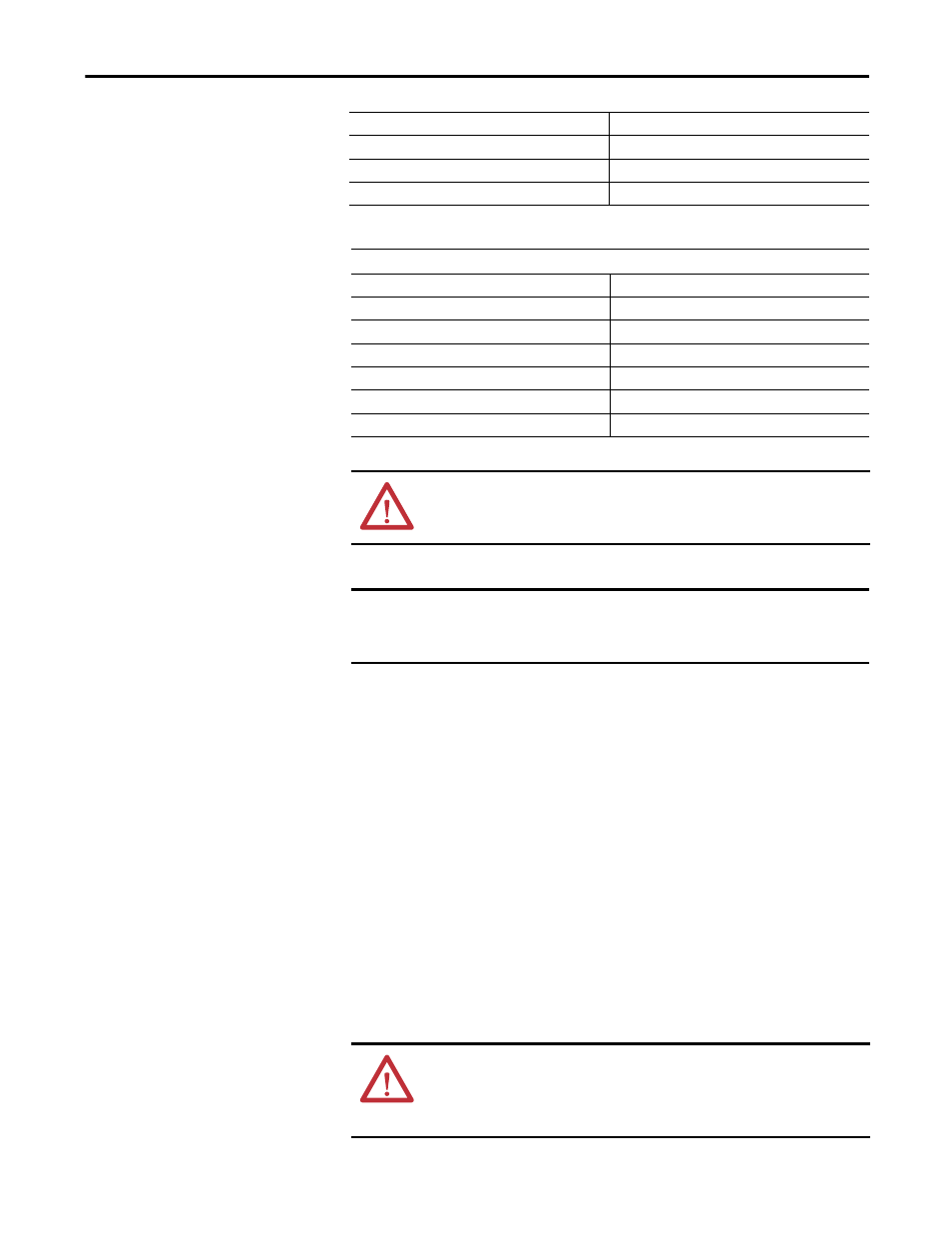
Table 14 - CT Secondary (Parameter 264)
The installer shall (1) provide one CT for each motor phase and shall (2) connect
the CT’s secondary leads to the appropriate sensing module power terminals.
The CTs shall be selected to be capable of providing the required VA to the
secondary load, which includes the E300 Sensing Module burden of 0.1 VA at
the rated secondary current and the wiring burden. Finally, the CT shall (1) be
rated for Protective Relaying to accommodate the high inrush currents associated
with motor startup and shall (2) have an accuracy of ≤±2% over its normal
operating range. Typical CT ratings include:
•
ANSI USA
•
CSA (Canada)
•
IEC (Europe)
•
Class C5 BO.1
•
Class 10L5
•
5 VA Class SP10
Parameter Type
UINT
Size (Bytes)
2
Scaling Factor
1
Units
Amps
CT Secondary (Parameter 264)
Default Value
5
Minimum Value
1
Maximum Value
65535
Parameter Type
UINT
Size (Bytes)
2
Scaling Factor
1
Units
Amps
ATTENTION: Improper configuration of the CT Ratio parameters can result in
the E300 Electronic Overload Relay reporting inaccurate motor operational data
and possible motor damage.
IMPORTANT
The E300 Electronic Overload Relay will trip on a configuration fault when the
FLA setting is outside of the legal range of the selected CT Ratio settings. The
TRIP/WARN LED status indicator will flash red 3-long, 8-short blinking pattern.
ATTENTION: The improper selection of a current transformer can result in the
E300 Electronic Overload Relay reporting inaccurate motor operational data and
possible motor damage. The selected current transformer must be rated for
protective relaying applications.