Total apparent power, L1 power factor, L2 power factor power – Rockwell Automation 592- E300 Overload Relay User Manual User Manual
Page 252
252
Rockwell Automation Publication 193-UM015B-EN-P - June 2014
Chapter 7 Metering and Diagnostics
Total Apparent Power
Total Apparent Power (Parameter 75) reports the total apparent power of the
monitored power conductors in kVA or MVA depending on the configuration
value for Power Scale (Parameter 377). When Single or Three Phase (Parameter
176) is set to
Three Phase, Total Apparent Power is calculated as follows:
Total Apparent Power = (L1 Apparent Power + L2 Apparent Power + L3
Apparent Power)
When Single or Three Phase (Parameter 176) is set to
Single Phase, Total
Apparent Power is calculated as follows:
Total Apparent Power = (L1 Apparent Power + L2 Apparent Power)
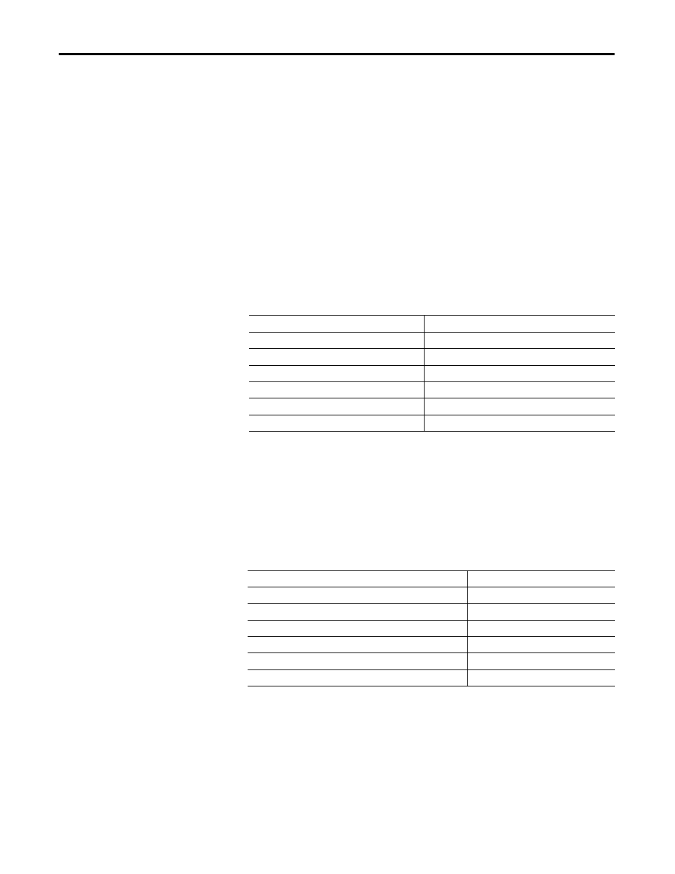
Table 280 - Total Apparent Power (Parameter 75)
L1 Power Factor
L1 Power Factor (Parameter 76) reports the power factor for line 1 in percentage.
When Voltage Mode (Parameter 352) is set to any
Delta base setting, L1 Power
Factor is set to 0.
Table 281 - L1 Power Factor (Parameter 76)
L2 Power Factor Power
L2 Power Factor (Parameter 77) reports the power factor for line 2 in percentage.
When Voltage Mode (Parameter 352) is set to any
Delta base setting, L2 Power
Factor is set to 0.
Default Value
0.000
Minimum Value
0.000
Maximum Value
2000000.000
Parameter Type
DINT
Size (Bytes)
4
Scaling Factor
1000
Units
kVA or MVA
Default Value
0.0
Minimum Value
-100.0
Maximum Value
100.0
Parameter Type
INT
Size (Bytes)
2
Scaling Factor
10
Units
%