Expansion bus peripherals, Figure 8 - expansion bus peripherals, Figure 9 - expansion operator stations – Rockwell Automation 592- E300 Overload Relay User Manual User Manual
Page 25
Rockwell Automation Publication 193-UM015B-EN-P - June 2014
25
Installation and Wiring Chapter 2
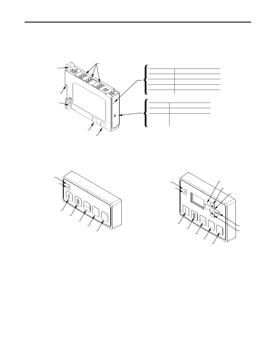
Expansion Bus Peripherals
The E300 Electronic Overload Relay offers a range of Expansion Digital and
Analog I/O modules that simply connect to the E300 Electronic Overload
Relay’s Expansion Bus.
Figure 8 - Expansion Bus Peripherals
Users can also add one of the two available operator stations to the end of the
Expansion Bus.
Figure 9 - Expansion Operator Stations
The following illustrations show how to mount and connect the E300 Electronic
Overload Relay expansion bus I/O modules, expansion power supplies, and
operator stations.
Module Number Selector
Note: If the expansion bus does not have an operator station, then the
last expansion module number must be set to terminated.
Panel Mount
Hole
DIN Rail Mount
Color
Status LED
Off
Blinking Green
No power applied
Description
Module OK with no connection
Removable I/O Terminals
Expansion Bus In
Expansion Bus Out
Panel Mount Hole
1
1T2T
3T
4T
2 3 4
Green
Module OK and active
Red
Error Detected
Number
1 - 4
1T - 4T
Module number
Description
Module number with
expansion bus terminating
resistor applied
Start Forward / Speed 1
Start Reverse / Speed 2
Local / Remote
Stop
Reset
Start Forward / Speed 1
Start Reverse / Speed 2
Local / Remote
Stop
Up
Down
Reset
Escape
Power LED
Trip / Warn LED
Power LED
Trip / Warn LED
Enter
Select
0
RESET
LOCA
L
REMO
TE
0
RESET
SELEC
T
ESC
REMO
TE
LOCA
L
Control Station
Diagnostic Station