Rockwell Automation 592- E300 Overload Relay User Manual User Manual
Page 143
Rockwell Automation Publication 193-UM015B-EN-P - June 2014
143
Protective Trip and Warning Functions Chapter 5
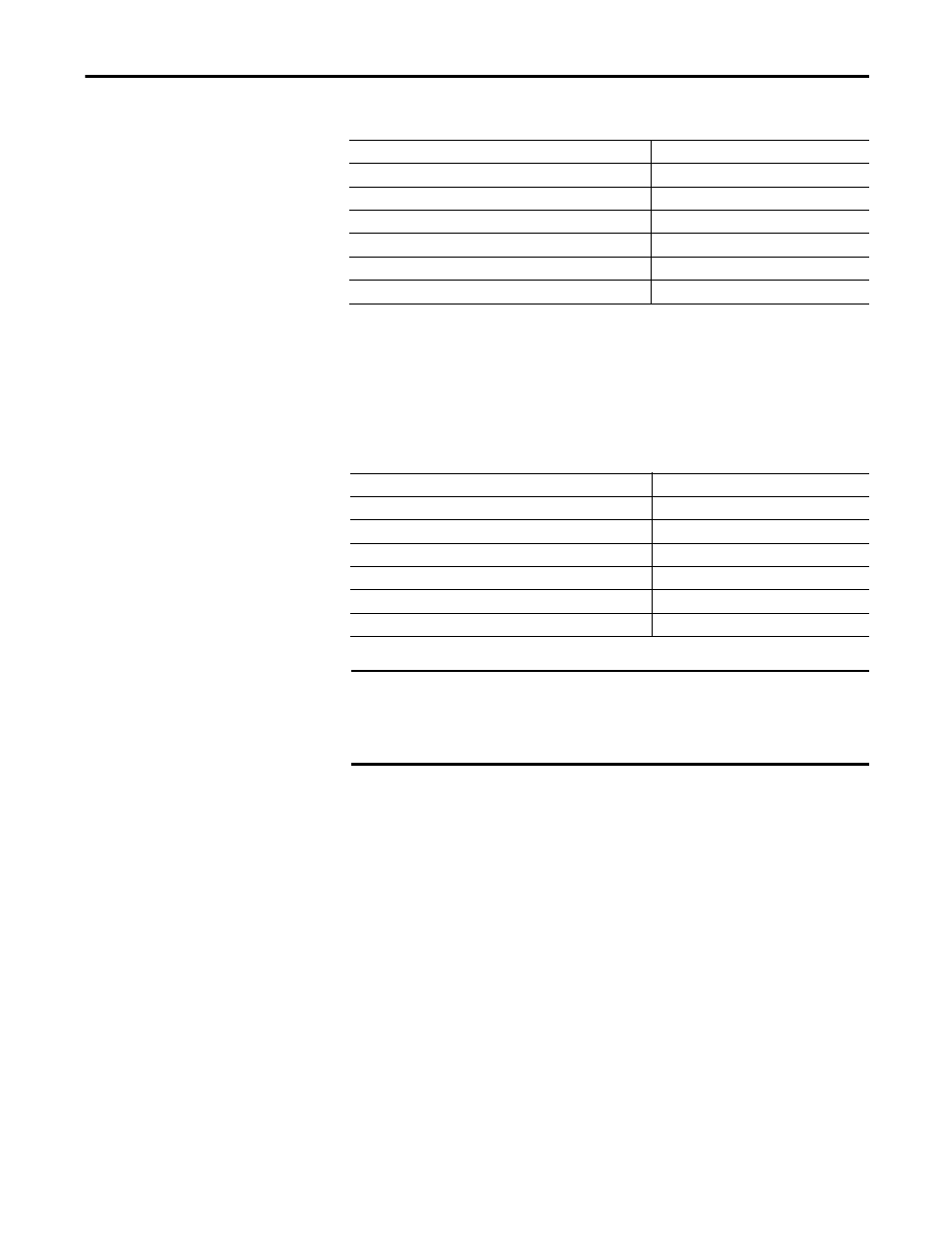
Table 130 - Voltage Imbalance Trip Delay (Parameter 366)
Voltage Imbalance Trip Level
Voltage Imbalance Trip Level (Parameter 367) allows the installer to define the
percentage at which the E300 Electronic Overload Relay will trip on a voltage
imbalance. It is user-adjustable from 10…100%.
Table 131 - Voltage Imbalance Trip Level (Parameter 367)
Voltage Imbalance Warning
The E300 Electronic Overload Relay will indicate a voltage imbalance warning
if:
•
No warning currently exists
•
Voltage Imbalance Warning is enabled
•
Voltage is present
•
Voltage Imbalance Inhibit Time has expired
•
The Voltage Imbalance (Parameter 61) is greater than the Voltage
Imbalance Warning Level
When the Voltage Imbalance Warning conditions are satisfied, the:
•
TRIP/WARN LED will flash a yellow red 1-long / 3-short blink pattern
•
Bit 2 in Voltage Warning Status (Parameter 11) will set to 1
•
Bit 1 in Device Status 0 (Parameter 20) will set to 1
Default Value
1.0
Minimum Value
0.1
Maximum Value
25.0
Parameter Type
USINT
Size (Bytes)
1
Scaling Factor
10
Units
Sec
Default Value
15
Minimum Value
10
Maximum Value
100
Parameter Type
USINT
Size (Bytes)
1
Scaling Factor
1
Units
%
IMPORTANT
The Voltage Imbalance Inhibit Timer starts after a phase voltage transitions
from 0V to 20V L-L. The E300 Electronic Overload Relay does not begin
monitoring for a voltage imbalance condition until the Voltage Imbalance
Inhibit Time expires.