Structure – FUJITSU F2MCTM-16LX User Manual
Page 91
75
CHAPTER 3 INTERRUPTS
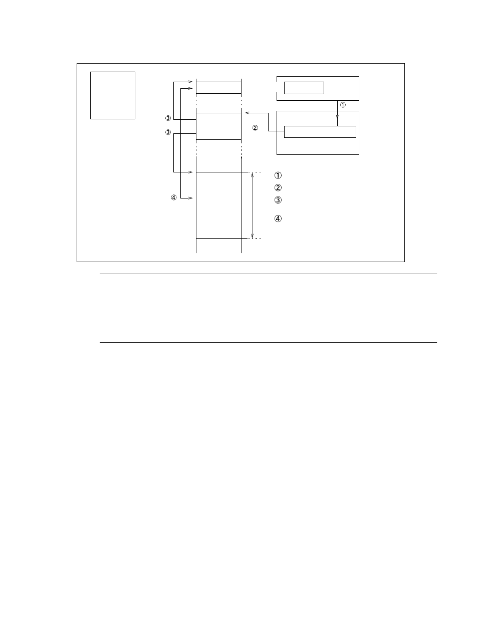
Figure 3.7-1 Outline of Extended Intelligent I/O Service
Note:
•
The area that can be specified by IOA is between 000000
H
and 00FFFF
H
.
•
The area that can be specified by BAP is between 000000
H
and FFFFFF
H
.
•
The maximum transfer count that can be specified by DCT is 65,536.
■
Structure
EI
2
OS is handled by the following 4 sections:
Internal resources
Interrupt enable and request bits: Used to control interrupt requests from resources.
Interrupt controller
ICR: Assigns interrupt levels, determines the priority levels of simultaneously requested interrupts, and
selects the EI
2
OS operation.
CPU
I and ILM: Used to compare the requested and current interrupt levels and to identify the interrupt
enable status
Microcode: EI
2
OS processing step
RAM
Descriptor: Describes the EI
2
OS transfer information.
by
by BAP
by IOA
ISD
by ICS
· · · · · · · · · · · · · · ·
CPU
Memory space
I/O register
Buffer
Peripheral
Interrupt request
Interrupt control register
Interrupt controller
I/O register
DCT
I/O requests transfer.
Interrupt controller selects descriptor.
Transfer source and destination
are read from descriptor.
Data is transferred between I/O
and memory.