FUJITSU F2MCTM-16LX User Manual
Page 446
430
CHAPTER 20 LIN-UART
where a is the value of the ICU data register after the first interrupt
where b is the value of the ICU data register after the second interrupt
Note:
As shown in the LIN slave mode, when the BGR value newly calculated by synch field generates
±15%
or more baud rate error, do not set the baud rate.
For the correspondence between other LIN-UARTs and ICUs, see "13.5 Explanation of Operation of 16-
bit Free-run Timer" and "13.6 Explanation of Operation of Input Capture".
●
LIN Synch Break Detection Interrupt and Flags
If a LIN Synch break is detected in the slave mode, the LIN Break Detected (LBD) Flag of the ESCR is set
to "1". This causes an interrupt, if the LIN Break Interrupt Enable (LBIE) bit is set to 1.
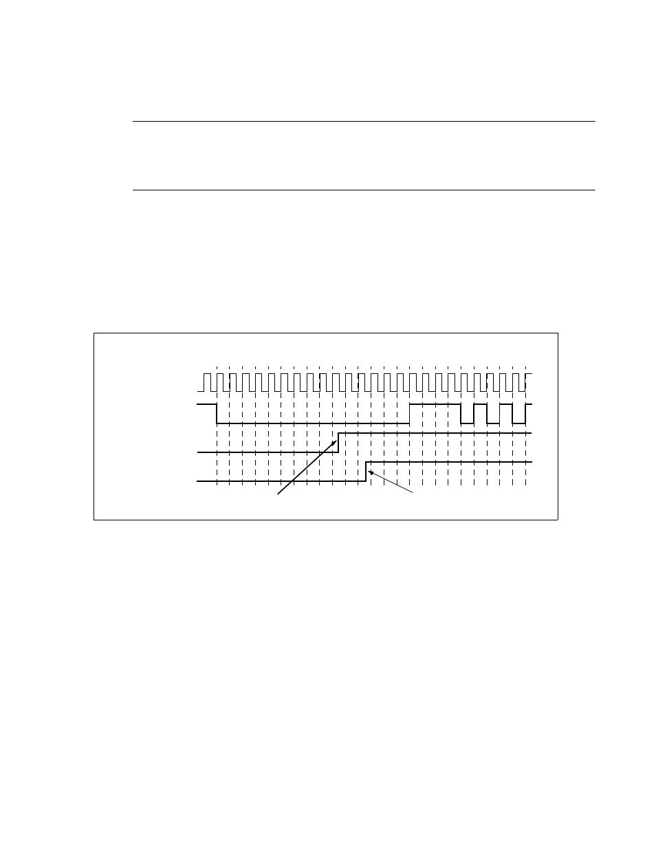
Figure 20.7-7 LIN Synch Break Detection and Flag Set Timing.
The figure above demonstrates the LIN synch break detection and flag set timing.
Note, that if reception is enabled (RXE = 1) and reception interrupt is enabled (RIE = 1) the Reception Data
Framing Error (FRE) flag bit of the SSR will cause a reception interrupt 2 bit times ("8N1") earlier than the
LIN break interrupt, so it is recommended to turn off RXE, if a LIN break is expected.
LIN synch break detection is only supported in operation mode 3.
Figure 20.7-8 shows a typical start of a LIN message and the behavior of the LIN-UART.
FRE
(RXE=1)
LBD
(RXE=0)
0 1 2 3 4 5 6 7 8 9 10 11 12 13 14 15
Serial clock cycle#
Serial
clock
Serial input
(LIN bus)
Reception interrupt occurs, if RXE=1
Reception interrupt occurs, if RXE=0