Figure 20.7-8 s – FUJITSU F2MCTM-16LX User Manual
Page 447
431
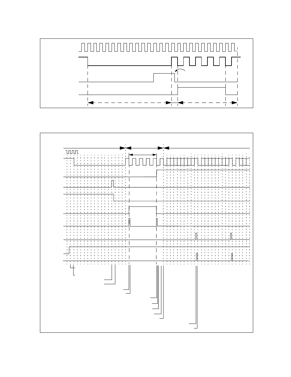
CHAPTER 20 LIN-UART
Figure 20.7-8 LIN-UART Behavior as Slave in LIN Mode
●
LIN bus timing
Figure 20.7-9 LIN Bus Timing and LIN-UART Signals
LBD
Synch field
Serial
clock
Serial input
(LIN bus)
ICU input
signal
(LSYN)
LBR cleared by CPU
Synch break (at 14-bit setting)
bus
RXE
LBD
(IRQ0)
RDRF
IRQ (ICU)
IRQ(ICU)
(SIN)
(IRQ0)
IRQ(ICU)
LIN
LBIE
RIE
No clock used
(calibration frame)
Old serial clock
New (calibrated) serial clock
ICU count
Reception inter-
rupt enable
LIN break begins
LIN break detected and Interrupt
IRQ cleared by CPU (LBD->0)
IRQ cleared: Begin of ICU
IRQ cleared: Calculate & set new baud rate
LBIE disable
Reception enable
Falling edge of start bit
Store one byte of received data to RDR
RDR read by CPU
Read
RDR
by CPU
ICU input
(LSYN)
See also other documents in the category FUJITSU Hardware:
- XG Series P3NK-4452-01ENZD (614 pages)
- FPCAC14C (1 page)
- MCJ3230SS (161 pages)
- MBA3073NC (138 pages)
- T5140 (102 pages)
- T5140 (76 pages)
- MAM3367MC/MP (152 pages)
- MPC3045AH (185 pages)
- MB2142-02 (23 pages)
- MB15F86UL (6 pages)
- MHS2030AT (40 pages)
- MHW2100BS (296 pages)
- MHK2060AT (227 pages)
- Disk Drives MHK2060AT (227 pages)
- MCM3064SS (170 pages)
- Mainboard D1561 (45 pages)
- MHC2040AT (219 pages)
- D1961 (45 pages)
- DISK DRIVES MHM2100AT (231 pages)
- MHR2010AT (250 pages)
- MHZ2120BJ (320 pages)
- MCE3064AP (175 pages)
- LQFP-64P (16 pages)
- Solaris PCI GigabitEthernet 3.0 (115 pages)
- MAY2036RC (94 pages)
- MAB3091 (142 pages)
- MPE3XXXAT (191 pages)
- MHV2040AH (40 pages)
- MHW2040AC (278 pages)
- ETERNUSmgr P2X0-0202-01EN (64 pages)
- VSS Hardware Provider 2.1 (134 pages)
- MAG3182FC (61 pages)
- MAU3147NC/NP (130 pages)
- MAX3147RC (94 pages)
- MHV2160BT (296 pages)
- MHV2040AT (280 pages)
- MAW3300NC/NP (130 pages)
- DeskPower E623 (50 pages)
- MAG3182LC (133 pages)
- OPTICAL DISK DRIVES MDG3064UB (42 pages)
- MHF2021AT (225 pages)
- MHR2040AT (40 pages)
- Single Drive FTM7926FB (1 page)
- PG-FCS103 (98 pages)
- MAS3735FC (114 pages)