8 register bank, Register bank – FUJITSU F2MCTM-16LX User Manual
Page 62
46
CHAPTER 2 CPU
2.8
Register Bank
A register bank consists of eight words. The register bank can be used as the following
general-purpose registers for arithmetic operations: byte registers R0 to R7, word
registers RW0 to RW7, and long word registers RL0 to RL3. In addition, the register
bank can be used as instruction pointers.
RL0 to RL3 are used as the linear pointer that directly accesses entire space.
■
Register Bank
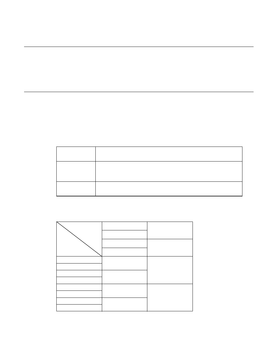
Table 2.8-1 lists the functions of the registers. Table 2.8-2 indicates the relationship between the registers.
In the same manner as for an ordinary RAM area, the register bank values are not initialized by a reset. The
status before a reset is maintained. When the power is turned on, however, the register bank will have an
undefined value.
●
Direct page register (DPR) H > DPR specifies addr8 to addr15 of the instruction operands in direct addressing mode as shown in Figure Table 2.8-1 Register Functions R0 to R7 Used as operands of instructions. RW0 to RW7 Used as pointers. RL0 to RL3 Used as long pointers. Table 2.8-2 Relationship between Registers RW0 RL0 RW1 RW2 RL1 RW3 R0 RW4 RL2 R1 R2 RW5 R3 R4 RW6 RL3 R5 R6 RW7 R7
Note: R0 is used as a counter for barrel shift and normalization instructions.
Used as operands of instructions.
Note: RW0 is used as a counter for string instructions.
Used as operands of instructions.