FUJITSU F2MCTM-16LX User Manual
Page 206
190
CHAPTER 11 TIMEBASE TIMER
■
Operation as Oscillation Stabilization Wait Time Timer
The timebase timer can be used as the oscillation stabilization wait time timer for the main clock and PLL
clock.
The oscillation stabilization wait time is the time elapsed from when the timebase timer counter increments
from "0" until the set oscillation stabilization wait time select bit overflows (carrying).
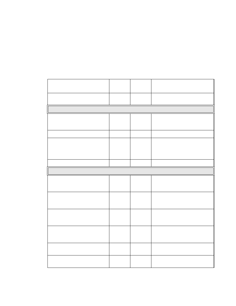
Table 11.5-1 shows clearing conditions and oscillation stabilization wait time of timebase timer.
Table 11.5-1 Clearing Conditions and Oscillation Stabilization Wait Time of Timebase
Timer (1/2)
Operation
Counter
clear
TBOF
clear
Oscillation stabilization wait time
Writing "0" to timebase timer
counter clear bit (TBTC: TBR)
❍
❍
Reset
Power-on reset
❍
❍
Transition to main clock mode after
oscillation stabilization wait time of
main clock completed
Watchdog reset
✕
❍
None
External reset
Low voltage detection reset
CPU operation detection reset
Clock supervisor reset
✕
❍
None
Software reset
✕
❍
None
Switching clock mode
Main clock
→ PLL clock
(CKSCR: MCS=1
→ 0)
❍
❍
Transition to PLL clock mode after
oscillation stabilization wait time of
PLL clock completed
Main clock
→ sub clock
(CKSCR: SCS=1
→ 0)
✕
✕
Transition to sub clock mode after
oscillation stabilization wait time of
sub clock completed
Sub clock
→ main clock
(CKSCR: SCS=0
→ 1)
❍
❍
Transition to main clock mode after
oscillation stabilization wait time of
main clock completed
Sub clock
→ PLL clock
(CKSCR: MCS=0, SCS=0
→ 1)
❍
❍
Transition to PLL clock mode after
oscillation stabilization wait time of
main clock completed
PLL clock
→ main clock
(CKSCR: MCS=0
→ 1)
✕
✕
None
PLL clock
→ sub clock
(CKSCR: MCS=0, SCS=1
→ 0)
✕
✕
None