Table b.5-2 and table b.5-3 s – FUJITSU F2MCTM-16LX User Manual
Page 611
595
APPENDIX B Instructions
Note:
When an external data bus is used, the cycle counts during which an instruction is made to wait by
ready input or automatic ready must also be added.
Note:
•
When an external data bus is used, the cycle counts during which an instruction is made to wait by
ready input or automatic ready must also be added.
•
Actually, instruction execution is not delayed by every instruction fetch. Therefore, use the correction
values to calculate the worst case.
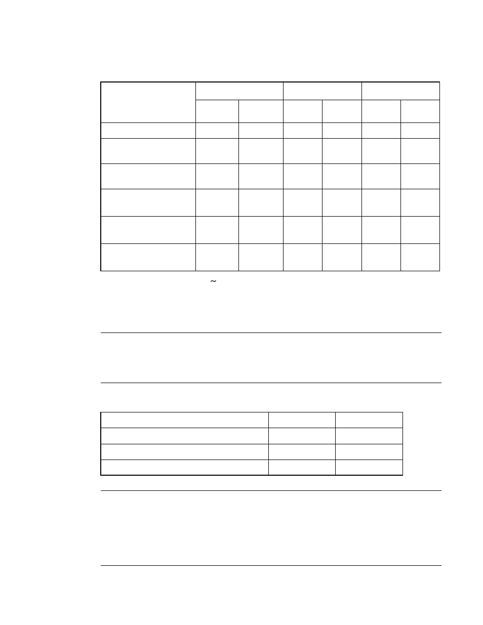
Table B.5-2 Cycle Count Correction Values for Counting Execution Cycles
Operand
(b) byte
*1
(c) word
*1
(d) long
*1
Cycle
count
Access
count
Cycle
count
Access
count
Cycle
count
Access
count
Internal register
+0
1
+0
1
+0
2
Internal memory
Even address
+0
1
+0
1
+0
2
Internal memory
Odd address
+0
1
+2
2
+4
4
External data bus
*2
16-bit even address
+1
1
+1
1
+2
2
External data bus
*2
16-bit odd address
+1
1
+4
2
+8
4
External data bus
*2
8-bits
+1
1
+4
2
+8
4
*1: (b), (c), and (d) are used for
(cycle count) and B (correction value) in "B.8 F
*2: When an external data bus is used, the number of cycles during which an instruction is made to wait
by ready - signal input or automatic ready must also be added.
Table B.5-3 Cycle Count Correction Values for Counting Instruction Fetch Cycles
Instruction
Byte boundary
Word boundary
Internal memory
-
+2
External data bus 16-bits
-
+3
External data bus 8-bits
+3
-