FUJITSU F2MCTM-16LX User Manual
Page 39
23
CHAPTER 1 OVERVIEW
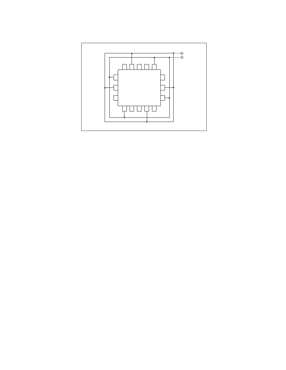
Figure 1.7-2 Power Supply Pins (V
CC
/V
SS
)
●
Pull-up/down resistors
The MB90360 Series does not support internal pull-up/down resistors (except Port2:
programmable pull-up resistors). Use pull-up/down handling where needed.
●
Crystal Oscillator Circuit
Noises around X0 or X1 pins may be possible causes of abnormal operations. Make sure to provide bypass
capacitors via shortest distance from X0, X1 pins, crystal oscillator (or ceramic resonator) and ground lines,
and make sure, to the utmost effort, that lines of oscillation circuit not cross the lines of other circuits.
It is highly recommended to provide a printed circuit board art work surrounding X0 and X1 pins with a
ground area for stabilizing the operation.
●
Turning-on Sequence of Power Supply to A/D Converter and Analog Inputs
Make sure to turn on the A/D converter power supply (AV
CC
, AVR) and analog inputs (AN0 to AN15)
after turning-on the digital power supply (V
CC
).
Turn-off the digital power supply after turning off the A/D converter power supply and analog inputs. In
this case, make sure that the voltage not exceed AVR or AV
CC
.
●
Connection of Unused Pins of A/D Converter
Connect unused pins of A/D converter as AV
CC
= V
CC
, AV
SS
= AVR = V
SS
.
Vcc
Vss
Vss
Vcc
Vss
Vcc
Vcc
Vss
Vcc
Vss
MB90360
series