FUJITSU F2MCTM-16LX User Manual
Page 427
411
CHAPTER 20 LIN-UART
20.5.2
Transmission Interrupt Generation and Flag Set Timing
A transmission interrupt is generated when the transmission data is transferred from
transmission data register (TDR) to transmission shift register and transmission is
started.
■
Transmission Interrupt Generation and Flag Set Timing
When the data written to the TDR register is transferred to the transmission shift register and the
transmission is started, next data to be written is enabled (SSR: TDRE=1). Then, if transmission interrupt is
enabled (SSR: TIE=1), the transmission interrupt occurs. Because the TDRE bit is "read only", it only can
be cleared to "0" by writing data into TDR.
The following figure demonstrates the transmission operation and flag set timing for the four modes of
LIN-UART.
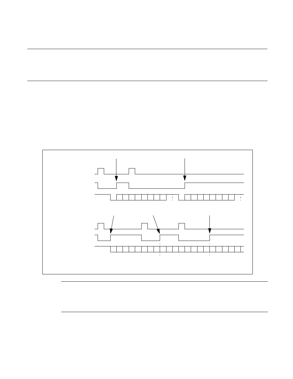
Figure 20.5-3 Transmission Operation and Flag Set Timing
Note:
The example in Figure 20.5-3 does not show all possible transmission options for mode 0. Here it is:
"8p1" (p = "E" [even] or "O" [odd]). Parity is not provided in mode 3 or 2, if SSM = 0.
TDRE
TDRE
ST D0 D1 D2 D3 D4 D5 D6 D7
P
AD
SP ST D0 D1 D2 D3 D4 D5 D6 D7
P
AD
SP
D0 D1 D2 D3 D4 D5 D6 D7 D0 D1 D2 D3 D4 D5 D6 D7 D0 D1 D2 D3 D4
Transmission interrupt occurs
Transmission interrupt occurs
Transmission interrupt occurs
Transmission interrupt occurs
Mode 0, 1 or 3:
write to TDR
Serial output
Mode 2 (SSM = 0):
write to TDR
Serial output
ST: Start bit D0 ... D7: data bits P: Parity SP: Stop bit AD: Address/data selection bit
(mode1)