FUJITSU F2MCTM-16LX User Manual
Page 325
309
CHAPTER 16 8-/16-BIT PPG TIMER
●
Output waveform in 8+8-bit PPG output operation mode
The High and Low pulse widths to be outputted are determined by adding 1 to the value in the PPG reload
register and multiplying it by the count clock cycle.
The equations for calculating the pulse width are shown below:
PL=T
× (Ln+1) × (Lm+1)
PH=T
× (Hn+1) × (Hm+1)
PL: Low width of output pulse of PPGm pin
PH: High width of output pulse of PPGm pin
L
n
: Values of 8 bits in PPG reload register (PRLLn)
H
n
: Values of 8 bits in PPG reload register (PRLHn)
L
m
: Values of 8 bits in PPG reload register (PRLLm)
H
m
: Values of 8 bits in PPG reload register (PRLHm)
T: Count clock cycle
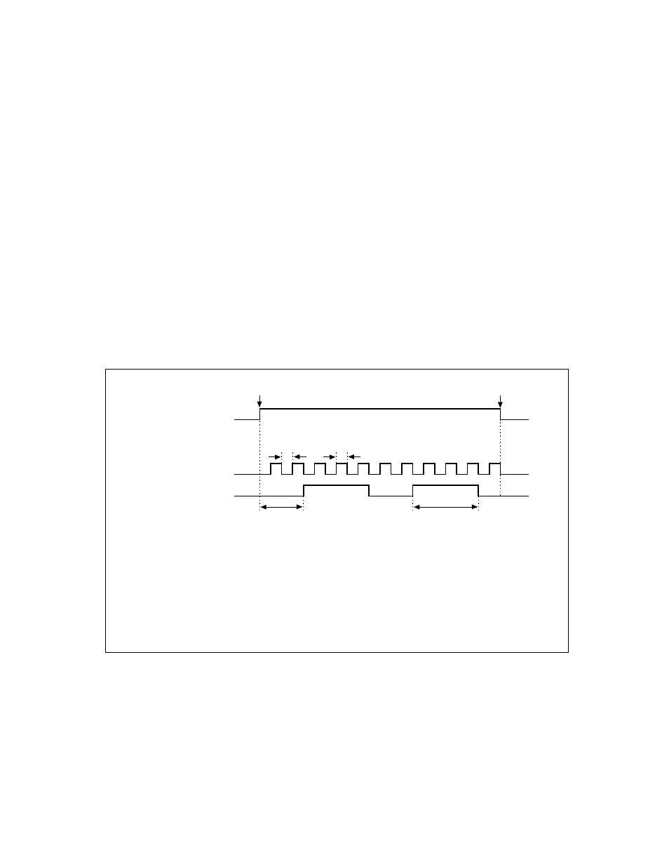
Figure 16.5-7 shows the output waveform in the 8+8-bit PPG output operation mode.
Figure 16.5-7 Output Waveform in 8+8-bit PPG Output Operation Mode
T
×
(L
0
+
1)
×
(L
1
+
1)
T
×
(H
0
+
1)
×
(H
1
+
1)
T
×
(L
0
+
1) T
×
(H
0
+
1)
Operation start
Operation stop
PPG operation enable
bit (PENn, PENm)
PPGn output pin
PPGm output pin
Ln : Values of 8 bits in PPG reload register (PRLLn)
Hn : Values of 8 bits in PPG reload register (PRLHn)
Hm : Values of 8 bits in PPG reload register (PRLLm)
Lm : Values of 8 bits in PPG reload register (PRLHm)
T
: Count clock cycle
Note: n = C, E
m = n + 1