FUJITSU F2MCTM-16LX User Manual
Page 222
206
CHAPTER 12 WATCHDOG TIMER
●
Checking reset factors
The reset factor bits in the watchdog timer control register (WDTC: PONR, WRST, ERST, SRST) can be
read after a reset to check the reset factors.
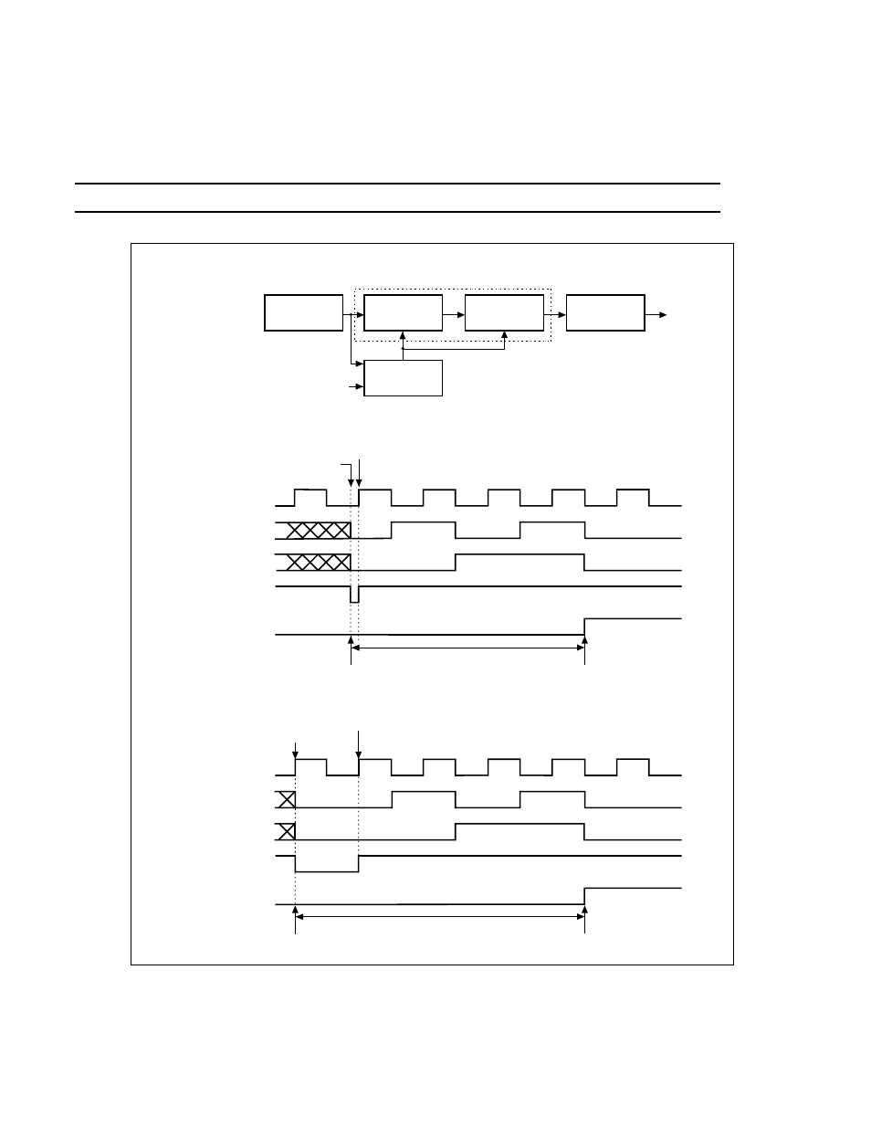
Figure 12.4-2 Relationship between Clear Timing and Interval Time of Watchdog Timer
Reference:
For details on the reset factor bit, see "CHAPTER 7 RESETS".
a
b
c
d
Clock
selector
Reset
circuit
[Watchdog timer block diagram]
2-division
circuit
Count enable
output circuit
2-division
circuit
2-bit counter
WTE bit
Count enable and clear
[Minimum interval time] When clear WTE bit immediately before rising of count clock.
Count clock a
2-division’s value b
2-division’s value c
Count enable
Reset signal d
Count start
Counter clear
7
×
(Count clock cycle/2)
WTE bit clear
Watchdog reset generation
[Maximum interval time] When clear WTE bit immediately after rising of count clock.
Count clock a
2-division’s value b
2-division’s value c
Count enable
Reset signal
Count start
Counter clear
9
×
(Count clock cycle/2)
WTE bit clear
Watchdog reset generation
Reset
signal