Register function – FUJITSU F2MCTM-16LX User Manual
Page 496
480
CHAPTER 21 CAN CONTROLLER
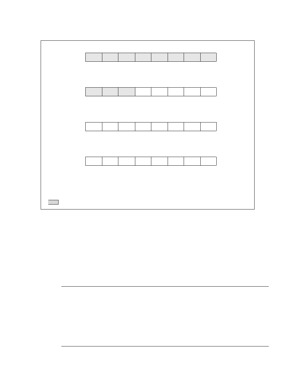
Figure 21.4-23 Configuration of the Acceptance Mask Register 1 (AMR1)
■
Register Function
●
0: Compare
Compare the bit (be set to "0") of the acceptance code (ID register IDRx for comparing with the received
message ID) corresponding to this bit with the bit of the received message ID. If there is no match, no
message is received.
●
1: Mask
Mask the bit of the acceptance code ID register (IDRx) corresponding to this bit. No comparison is made
with the bit of the received message ID.
Notes:
•
AMR0 and AMR1 should be set when all the message buffers (x) selecting AMR0 and AMR1 are
invalid (BVALx of the message buffer valid register (BVALR) is 0). Setting when the buffers are valid
(BVALx = 1) may cause unnecessary received messages to be stored.
•
To invalidate the message buffer (by setting the BVALR: BVAL bit to 0) while the CAN controller is
operating for CAN communication (the read value of the CSR: HALT bit is 0 and the CAN controller is
operating for CAN bus communication to enable transmission and reception), follow the procedure in
"21.13 Precautions when Using CAN Controller".
Address
bit7
bit6
bit5
bit4
bit3
bit2
bit1
bit0
AMR11(Byte0)
CAN1:
007D18
H
AM28
AM27
AM26
AM25
AM24
AM23
AM22
AM21
Reset value
XXXXXXXX
B
R/W
R/W
R/W
R/W
R/W
R/W
R/W
R/W
Address
bit15
bit14
bit13
bit12
bit11
bit10
bit9
bit8
AMR11(Byte1)
CAN1:
007D19
H
AM20
AM19
AM18
AM17
AM16
AM15
AM14
AM13
Reset value
XXXXXXXX
B
R/W
R/W
R/W
R/W
R/W
R/W
R/W
R/W
Address
bit7
bit6
bit5
bit4
bit3
bit2
bit1
bit0
AMR11(Byte2)
CAN1:
007D1A
H
AM12
AM11
AM10
AM9
AM8
AM7
AM6
AM5
Reset value
XXXXXXXX
B
R/W
R/W
R/W
R/W
R/W
R/W
R/W
R/W
Address
bit15
bit14
bit13
bit12
bit11
bit10
bit9
bit8
AMR11(Byte3)
CAN1:
007D1B
H
AM4
AM3
AM2
AM1
AM0
−
−
−
Reset value
XXXXXXXX
B
R/W
R/W
R/W
R/W
R/W
−
−
−
R/W
X
−
: Read/Write
: Undefined
: Unused
: Used bit in typical frame format