Receive overrun – FUJITSU F2MCTM-16LX User Manual
Page 507
491
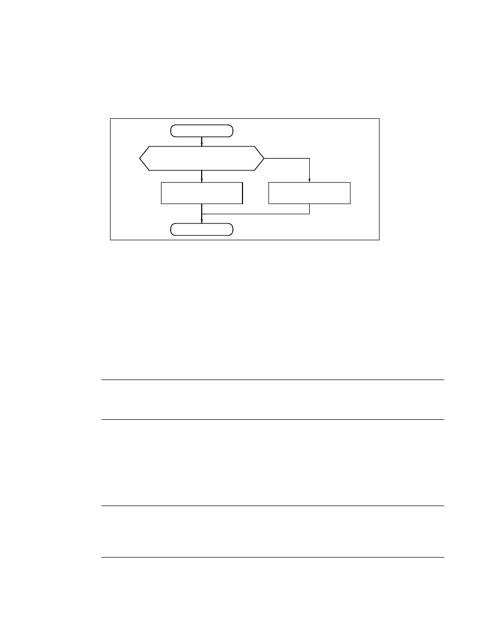
Figure 21.6-1 shows a flowchart for determining the message buffer (x) where received messages are to be
stored. It is recommended that message buffers be arranged in the following order: message buffers in
which each AMSR bit is set to All Bits Compare, message buffers using AMR0 or AMR1, and message
buffers in which each AMSR bit is set to All Bits Mask.
Figure 21.6-1 Flowchart Determining Message Buffer (x) where Received Messages Stored
■
Receive Overrun
When a message is stored in the message buffer with the corresponding RCx being already set to 1, it will
results in receive overrun. In this case, the corresponding ROVRx bit in the receive overrun register
ROVRR is set to 1.
■
Processing for Reception of Data Frame and Remote Frame
●
Processing for reception of data frame
RRTRx of the remote request receiving register (RRTRR) becomes 0.
TREQx of the transmission request register (TREQR) becomes 0 (immediately before storing the received
message). A transmission request for message buffer (x) having not executed transmission will be canceled.
Note:
A request for transmission of either a data frame or remote frame is canceled.
●
Processing for reception of remote frame
RRTRx becomes 1.
If TRTRx of the transmitting RTR register (TRTRR) is 1, TREQx becomes 0. As a result, the request for
transmitting remote frame to message buffer having not executed transmission will be canceled.
Notes:
•
A request for data frame transmission is not canceled.
•
For cancellation of a transmission request, see "21.5 Transmission of CAN Controller".
NO
YES
End
Start
Select the lowest-numbered
message buffer.
Are message buffers with RCx set to 0
or with AMSx.1 and AMSx.0 set to 00
B
found?
Select the lowest-numbered
message buffer from above
message buffer.