5 input level select register, Input level select register – FUJITSU F2MCTM-16LX User Manual
Page 192
176
CHAPTER 10 I/O PORTS
10.2.5
Input Level Select Register
The input level select register allows to switch from Automotive Hysteresis input levels
to CMOS Hysteresis input levels.
■
Input Level Select Register (ILSR)
The input level select register ILSR is located on addresses 0E
H
and 0F
H
.
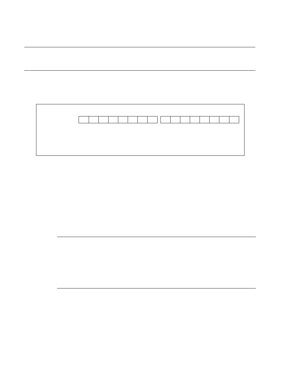
Figure 10.2-7 Input Level Select Register (ILSR)
bit 2, bit 4 to bit6 and bit8:IL2, IL4 to IL6, IL8
These bits set the input level of the corresponding port. IL2, IL4 to IL6, IL8 correspond to the port 2,
port 4 to port 6, port 8, respectively. Setting these bits to “0” selects the Automotive input level. Setting
these bits to “1” selects the CMOS hysteresis input level. The initial value of these bits depends on the
mode pin setting:
• For the flash memory mode, the initial value is “1” (TTL).
• For all other modes, the initial value is "0" (Automotive).
bit 0, bit 1, bit 3, bit 7 and bit 9 to bit 15: undefined
Reading from these bits is undefined. Writing to these bits is no effect.
Note:
The threshold of the corresponding input pin varies immediately after the setting of the input level
select register is changed.
Therefore, do not use the read value from the pin until 2 machine cycles are elapsed after the setting is
changed.
When the setting is changed, be sure to disable the corresponding resource.
ILSR1 : 00000F
H
ILSR0 : 00000E
H
R/W
R/W R/W R/W
R/W
15
14
13
12
11
10
9
8
7
6
5
4
3
2
1
0
−
IL8
IL6
IL5
IL4
IL2
−
X
X
X
X
X
X
0/1
X
0/1
0/1
0/1
X
0/1
X
X
−
−
−
−
−
−
−
−
−
−
X
−
−
−
−
−
−
−
−
−
−
R/W : Read/Write
−
: Unused
X
: Undefined
Address
Initial value: