2 block diagram of timebase timer, Block diagram of timebase timer – FUJITSU F2MCTM-16LX User Manual
Page 198
182
CHAPTER 11 TIMEBASE TIMER
11.2
Block Diagram of Timebase Timer
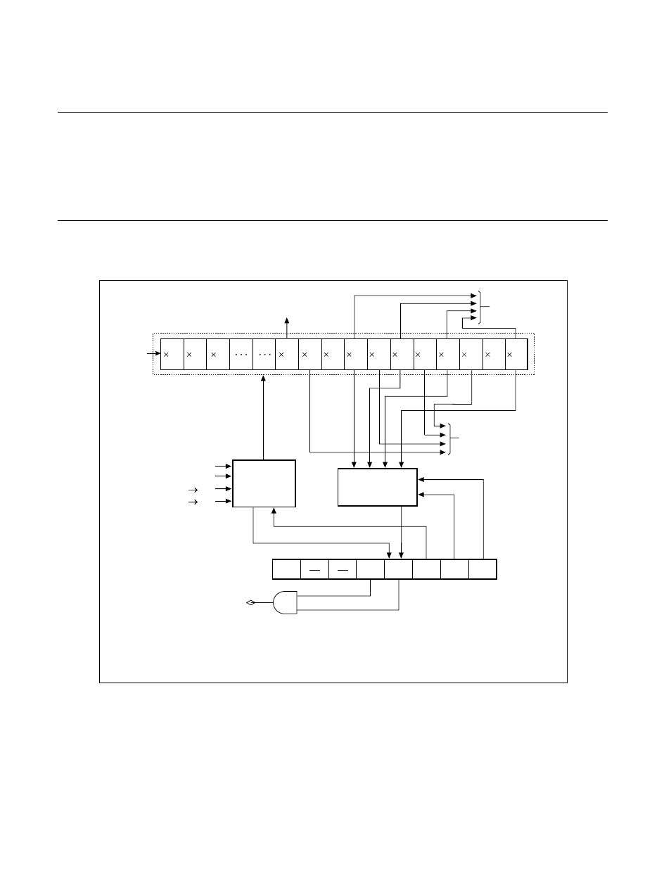
The timebase timer consists of the following blocks:
• Timebase timer counter
• Counter clear circuit
• Interval timer selector
• Timebase timer control register (TBTC)
■
Block Diagram of Timebase Timer
Figure 11.2-1 Block Diagram of Timebase Timer
The actual interrupt request number of the timebase timer is as follows:
Interrupt request number: #25 (19
H
)
2
1
/HCLK
CKSCR : MCS=1
0*
1
CKSCR : SCS=0
1*
2
OF
OF
OF
OF
TBIE TBOF
TBC1 TBC0
TBR
2
1
2
2
2
11
2
12
2
13
2
14
2
15
2
16
2
17
2
18
2
10
2
9
2
8
2
3
To PPG timer
Timebase timer counter
To watchdog
timer
To clock control part
oscillation stabilization
waiting time selector
Interval timer
selector
Counter
clear
circuit
Power-on reset
Stop mode
Timebase timer control register
(TBTC)
Timebase timer interrupt signal
OF
: Overflow
HCLK : Oscillation clock
*1
: For switching machine clock from main clock to PLL clock
*2
: For switching machine clock from sub clock to main clock
TBOF set
TBOF clear
Re-
served