Explanation of operation of dtp/external interrupt – FUJITSU F2MCTM-16LX User Manual
Page 343
327
CHAPTER 17 DTP/EXTERNAL INTERRUPTS
17.4
Explanation of Operation of DTP/External Interrupt
The DTP/external interrupt has an external interrupt function and a DTP function. The
setting and operation of each function are explained.
■
Setting of DTP/External Interrupt
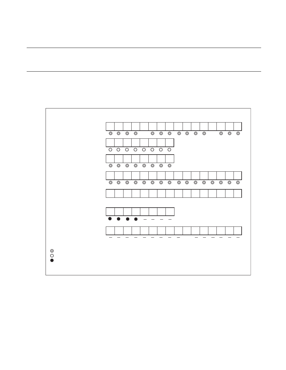
Using the DTP/external interrupt requires, the setting shown in Figure 17.4-1 .
Figure 17.4-1 Setting of DTP/External Interrupt
ICS0 ISE
IL1 IL0
IL2
ICS3 ICS2 ICS1
ICS0 ISE
IL1 IL0
IL2
ICS3 ICS2 ICS1
ICR interrupt control register
LB15
DDR port direction register
bit15 14
13
12
11
10
9
bit8 bit7
6
5
4
3
2
1
bit0
: Set 0
0
: Set 1
1
: Used bit
: Set the bit corresponding to used pin to 1
: Set the bit corresponding to used pin to 0
: Unused bit
Set the bit corresponding to pin used for DTP/external interrupt input to 0.
−
0
At DTP (EI
2
OS)
1
1
LB12 LA12
LA14 LB13
LA13
LA15 LB14
ELVR1
LB8 LA8
LB9 LA9
LA10
LB11 LA11 LB10
−
MOD2 MOD1
− CSL1 CSL0
−
−
CNTE TRG
INTE
UF
RELD
MOD0 OUTE OUTL
ER9 ER8
ER12 ER11 ER10
ER15 ER14 ER13
EIRR1
EN9 EN8
EN12 EN11 EN10
EN15 EN14 EN13
ENIR1
At using INT8R
TMCSR3
(timer control)
ADER5
(Analog input enable)
only using INT8,10,11,13E
ADE12
ADE15 ADE14 ADE13
ADE8
ADE11 ADE10 ADE9