6 input capture edge register (ice) – FUJITSU F2MCTM-16LX User Manual
Page 240
224
CHAPTER 13 16-Bit I/O TIMER
13.3.6
Input Capture Edge Register (ICE)
The input capture edge register has a function to indicate the selected edge direction
and to select whether the input signal is inputted from either external pin or LIN-UART.
By cooperating with the LIN-UART, the baud rate measurement at the LIN slave
operation can be performed.
The correspondence between ICE01 to ICE23 / channel name and input pin (UART)
name is shown as follows.
ICE01: input capture ch0, ch1 IN0(/UART0) IN1(/UART1)
ICE23: input capture ch2, ch3 IN2
IN3
■
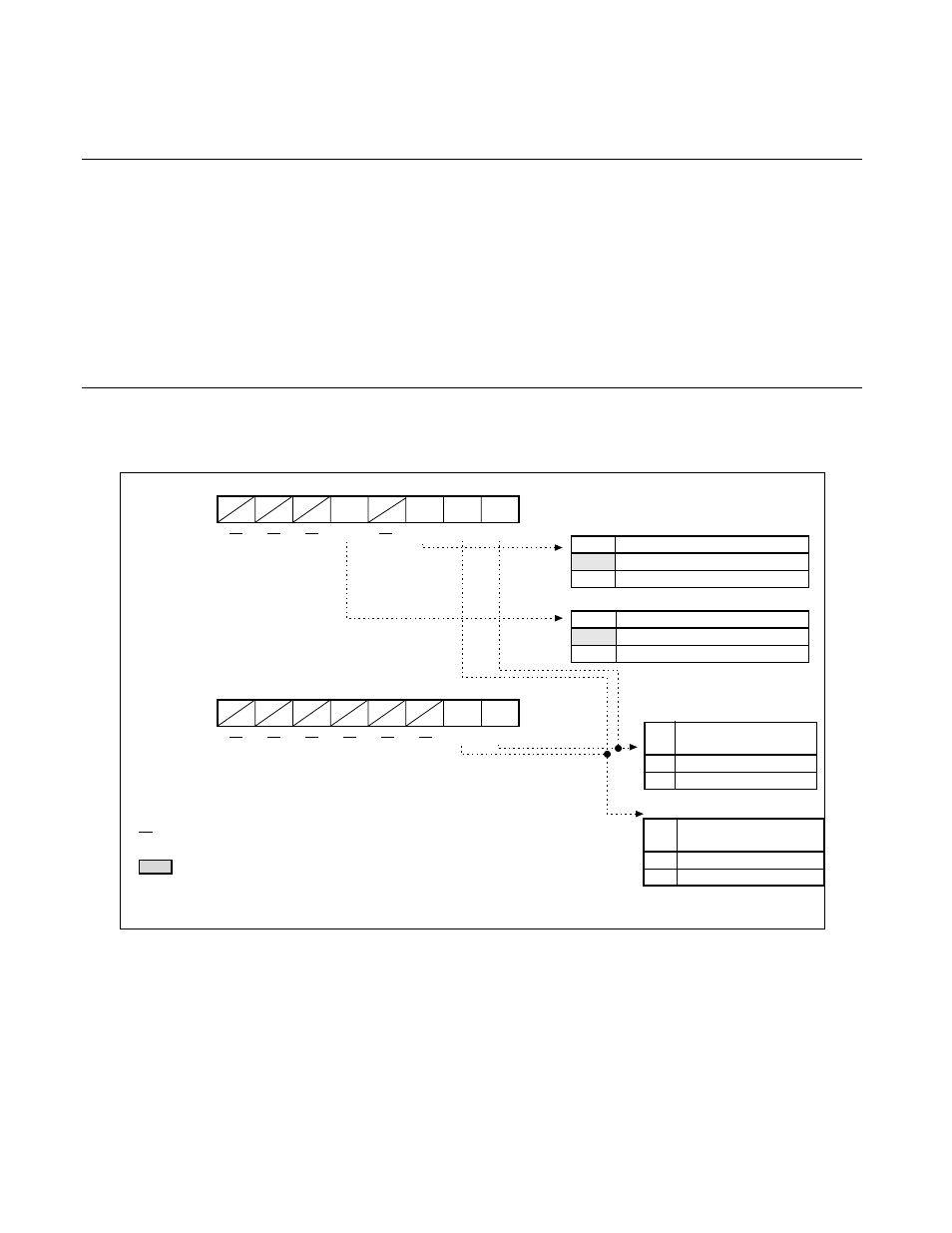
Input Capture Edge Register (ICE)
Figure 13.3-6 Input Capture Edge Register (ICE)
X
R
R/W
R
R
R/W
R/W
IEI0
IEI1
ICUS0
ICUS1
bit15 bit14 bit13 bit12 bit11 bit10 bit9
bit8
ICE01 : 000051
H
ICE23 : 000053
H
R
R
IEI2
IEI3
bit15 bit14 bit13 bit12 bit11 bit10 bit9
bit8
XXX0X0XX
B
XXXXXXXX
B
n = 0, 2 m = n+1
bit10
ICUS0
Input signal selection bit 0
0
Input signal of external pin IN0
1
Signal from UART0
Reset value
bit12
ICUS1
Input signal selection bit 1
0
Input signal of external pin IN1
1
Signal from UART1
bit8
IEIn
Detection edge
indication bit n
0
Detect falling edge
1
Detect rising edge
bit9
IEIm
Detection edge
indication bit m
0
Detect falling edge
1
Detect rising edge
Reset value
: Read/Write
: Read only
: Indeterminate
: Undefined
: Reset value