3 configuration of 16-bit i/o timer, Configuration of 16-bit i/o timer – FUJITSU F2MCTM-16LX User Manual
Page 232
216
CHAPTER 13 16-Bit I/O TIMER
13.3
Configuration of 16-bit I/O Timer
This section explains the pins, registers, and interrupt factors of the 16-bit I/O timer.
■
Pins of 16-bit I/O Timer
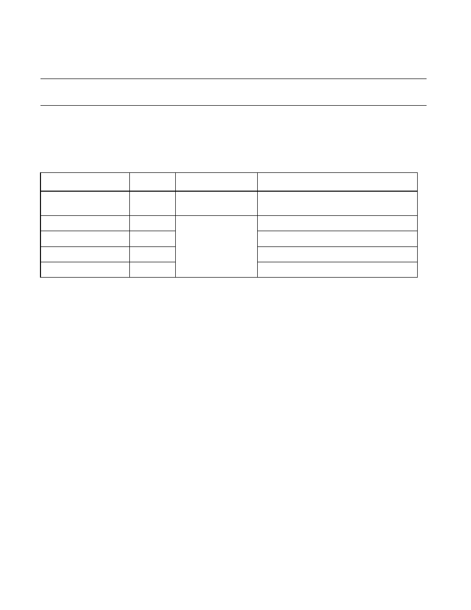
The pins of the 16-bit I/O timer serve as general-purpose I/O ports. Table 13.3-1 shows the pin functions
and the pin settings required to use the 16-bit I/O timer.
■
Generation of Interrupt Request from 16-bit I/O Timer
The 16-bit I/O timer can generate an interrupt request as a result of the following factors:
●
Timer counter overflow interrupt
If the overflow interrupt request is set to enable (TCCSL: IVFE=1), the interrupt is occurred by the
following factor:
•
16-bit free-run timer overflow
●
Input capture interrupt
If the input capture interrupt request is set to enable (ICS: ICE=1), if the trigger edge is detected by the
input capture pin, or if the trigger edge for the LIN slave baud rate measurement from the LIN-UART is
inputted, the interrupt request is generated.
Table 13.3-1 Pins of 16-bit I/O Timer
Channel
Pin Name
Pin Function
Setting to use the pin
16-bit free-run timer 0
P44/
FRCK0
General-purpose I/O port,
external clock input
Set as input port in port direction register (DDR).
Input capture 0
P24/IN0
General-purpose I/O
port, capture input
Set as input port in port direction register (DDR).
Input capture 1
P25/IN1
Set as input port in port direction register (DDR).
Input capture 2
P26/IN2
Set as input port in port direction register (DDR).
Input capture 3
P27/IN3
Set as input port in port direction register (DDR).