Figure 47 – Grass Valley Kalypso User Manual V.15.0 User Manual
Page 60
60
Kalypso — User Manual
Section 1 — System Overview
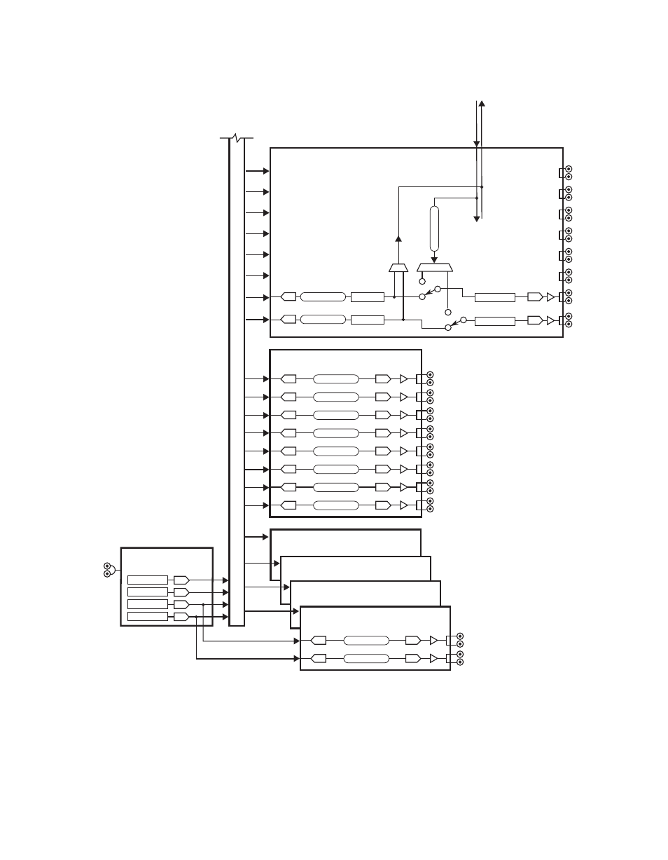
Figure 47. Simplified Kalypso Classic Video Flow Diagram (part 2)
0618_01_02_r1
Variable Delay
Shape/Pass
Variable Delay
Scale/Pass
V
ariable Delay
A
B
A
B
A
B
A
B
Ext. Eff. Send
Ext. Eff. Return
48
47
46
45
44
43
42
41
To/From All
8 Channels
Effects Send Module
Standard 8 Dual Outputs 41 - 48
2 of 8 Channels Shown
Channels Shown in Output Mode
Switches Up for Effects Send Mode
Output Mode with No Shape/Unshape:
Input A = Video or Key
Input B = Video or Key
Efects Send Mode:
Input A = Shaped or Unshaped Video
Input B = Key or Shaped Video
Output Module #1
Option 1 - 8 Dual Outputs
Variable Delay
1
Variable Delay
2
Variable Delay
3
Variable Delay
4
Variable Delay
5
Variable Delay
6
Variable Delay
7
Variable Delay
8
Sync Generator
Standard
Background 1
Background 2
Black
Test
Analog
525/625
Reference
Input
Output Module #2
Option 9 - 16 Dual Outputs
Output Module #3
Option 17 - 24 Dual Outputs
Output Module #5
Option 33 - 40 Dual Outputs
Output Module #4
Option 25 - 32 Dual Outputs
39 - Black
40 - Test
(33 - 38)
Variable Delay
Variable Delay
Unshape/Pass
Unscale/Pass
(Same as Output Module #1)
(Same as Output Module #1)
(Same as Output Module #1)
(Same as Output Module #1, except 39 and 40 dedicated)
Crosspoint Modules #1, #2, #3 (116 x 96 Matrix)
- Kalypso User Manual V.12.0 Apr 10 2007 Kalypso Reference Manual V.11.0 Kalypso Reference Manual V.12.0 Mar 16 2006 Kalypso Reference Manual V.12.0 Apr 10 2007 Kalypso Classic Installation V.11.0 Kalypso Classic Installation V.12.0 Mar 13 2006 Kalypso Classic Installation V.12.0 Apr 10 2007 Kalypso User Manual V.11.0 Kalypso User Manual V.12.0 Mar 16 2006 Kalypso Reference Manual V.15.1 Kalypso User Manual V.15.1 HD/Duo Kalypso Installation V.15.0 HD/Duo Kalypso Installation V.11.0 HD/Duo Kalypso Installation V.15.1 Kalypso Reference Manual V.15.0 Video Switcher