Kalypso facility example – Grass Valley Kalypso User Manual V.15.0 User Manual
Page 54
54
Kalypso — User Manual
Section 1 — System Overview
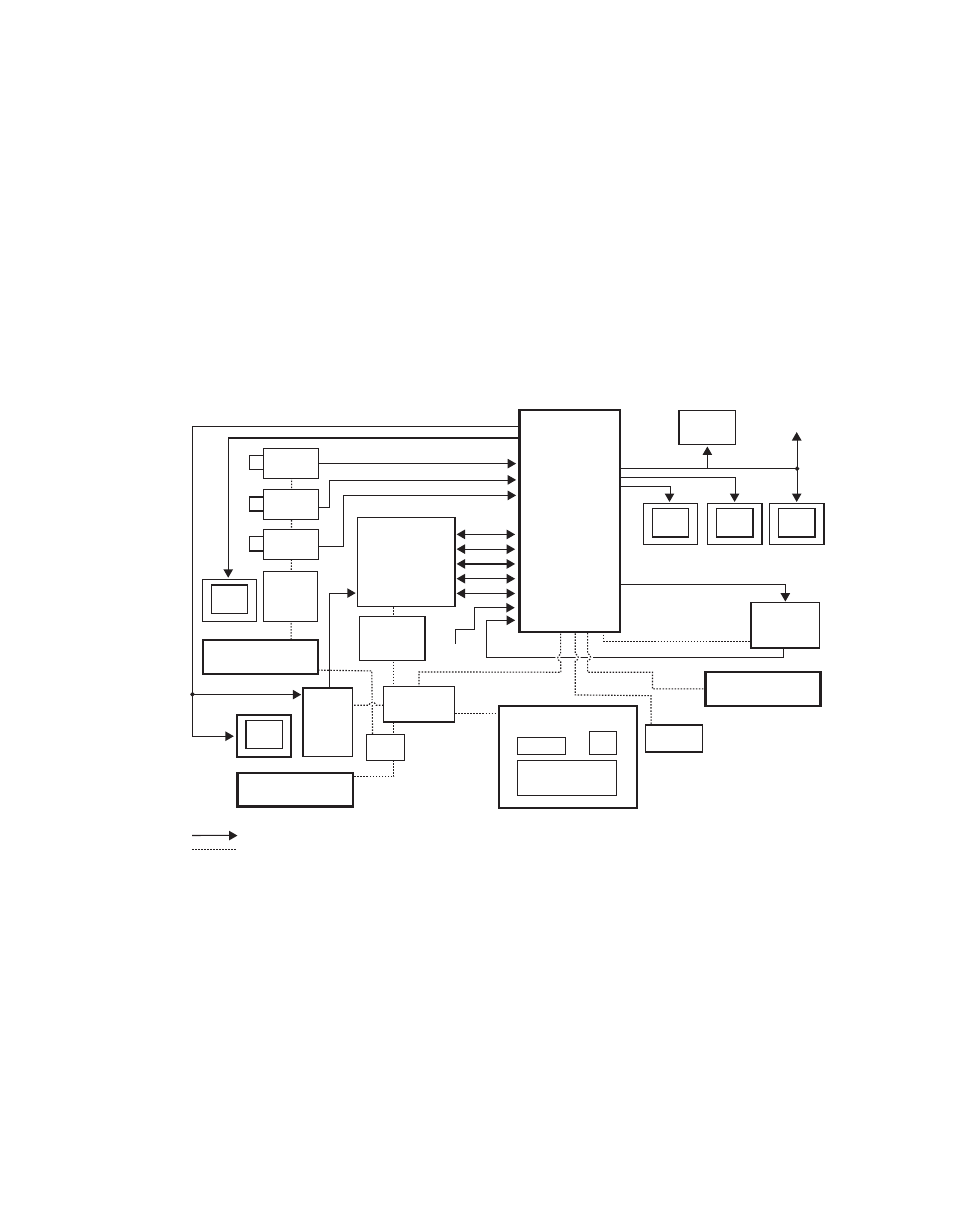
Kalypso Facility Example
A simplified diagram of a small live studio is shown in
facility the Kalypso Video Production Center has control of a portion of the
facility router for pre-selecting various sources into the switcher. The
camera control operator is able to remotely control a Kalypso Aux bus for
selecting camera views to shade. A Profile VDR operator also remotely con-
trols an Aux bus for recording selected iso cameras. After the clips have
been recorded to the Profile, the Technical Director at the Kalypso Main
panel can select and roll the Profile clips from his location. This facility also
has a Krystal DPM system configured for Effects Send. The Technical
Director can recall and run DPM effects from the Kalypso Main panel.
Figure 41. Basic Live Production Studio System Configuration Example
Program
Monitor
Preview
Monitor
Other
Monitors
Program Out
Master Control/
Transmitter
Video/Key (Effects Send)
Facility
Router
Frame
Cam 1
Cam 2
Cam 3
Video
Facility Router
Control
Camera
Shader
Video/Key (Effects Return)
Synchronous Serial (CPL)
NOTE: External Effects Send
only on Kalypso Classic
Serial
Reference
Black
Aux Bus Outputs
Profile
VDR
Facility LAN
32-Crosspoint
Remote Aux Panel
Remote Control Surface #1
0618_00_17_
r13
Video/Key
Kalypso Main Control Surface
Kalypso Control
Ethernet
Hub
32-Crosspoint
Remote Aux Panel
Remote Control Surface #2
Remote Control Surface #3
24-Crosspoint
Remote Aux Panel
Monitor
Monitor
Serial
LAN
Ethernet
Switch
Shot Box
Kalypso
Video
Processor
Frame
Joystick
DPM
1
VTR
1
Compatible DVEs: Krystal, GVeous/Dveous
Video or Key Signal
Control Line
Override
- Kalypso User Manual V.12.0 Apr 10 2007 Kalypso Reference Manual V.11.0 Kalypso Reference Manual V.12.0 Mar 16 2006 Kalypso Reference Manual V.12.0 Apr 10 2007 Kalypso Classic Installation V.11.0 Kalypso Classic Installation V.12.0 Mar 13 2006 Kalypso Classic Installation V.12.0 Apr 10 2007 Kalypso User Manual V.11.0 Kalypso User Manual V.12.0 Mar 16 2006 Kalypso Reference Manual V.15.1 Kalypso User Manual V.15.1 HD/Duo Kalypso Installation V.15.0 HD/Duo Kalypso Installation V.11.0 HD/Duo Kalypso Installation V.15.1 Kalypso Reference Manual V.15.0 Video Switcher