Grass Valley Kalypso User Manual V.15.0 User Manual
Page 46
46
Kalypso — User Manual
Section 1 — System Overview
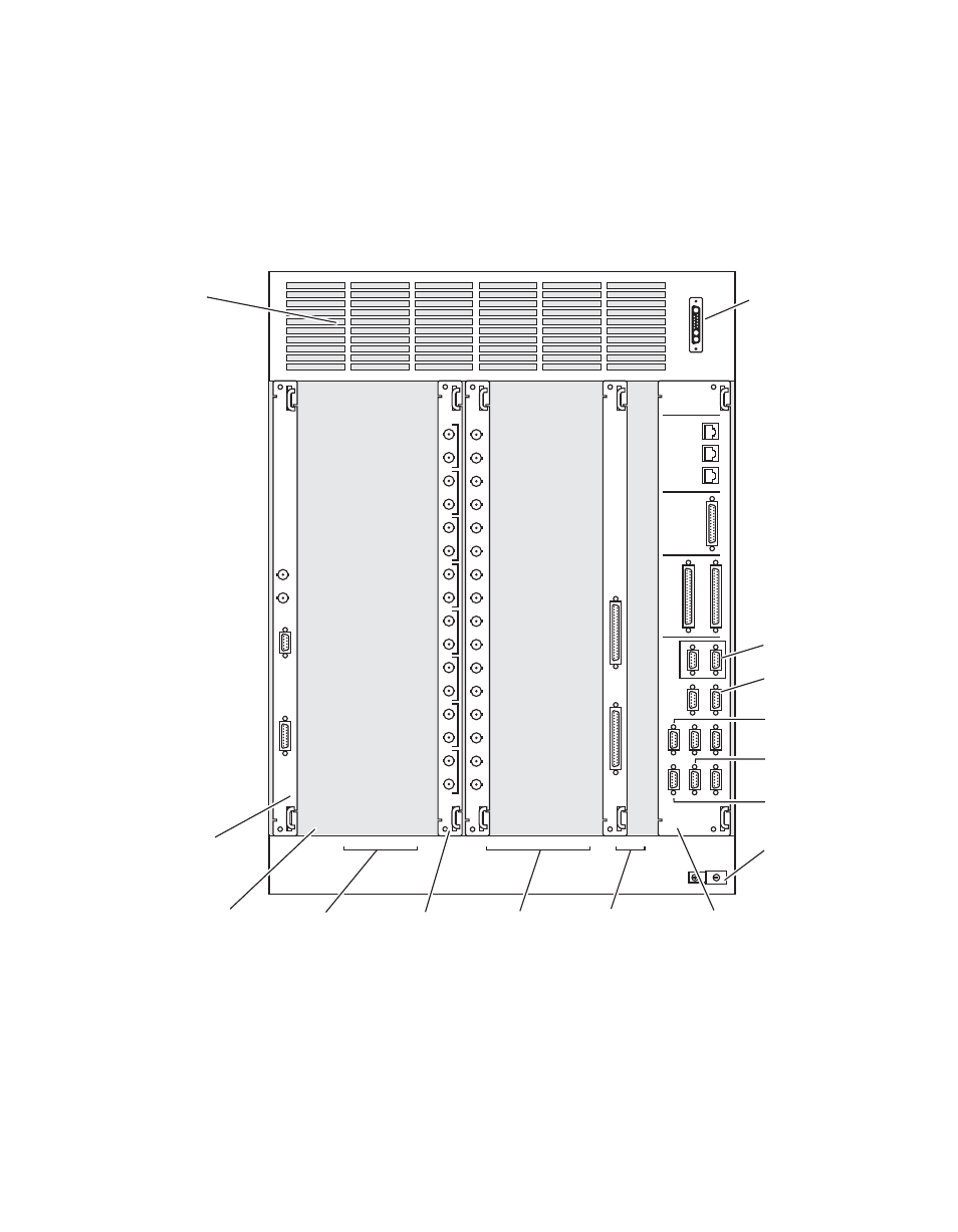
The standard 2-M/E Kalypso system includes one Input module and the
Effects Send module to support video inputs and outputs (
to four additional Input and Output modules can be installed. Slot B16
(labeled on the frame as Output 1, 1-8) is not available for use on a standard
2-M/E Kalypso system.
Figure 34. Standard 2-M/E Kalypso Video Processor Frame, Rear View
J4
ALARM
J3
TIMECODE IN
J2
J1
REFERENCE
REFERENCE
IN
OUT
IN
J6
J4
J5
J8
J7
J10
J9
2
1
J13
J12
5
4
J16
J15
8
J11
3
J14
6
7
422/
CPL
SERIAL
PORTS
GPI
COMM 1
COMM I/O
CONTROL
PANEL
LAN
J1
FACILITY
LAN
J2
STILL
STORE
LAN
J3
SERIAL
INPUT
J1
J2
J3
J4
J5
J6
J7
J8
J9
J10
J11
J12
J13
J14
J15
J16
EFFECTS
SEND
J1
J2
J3
J4
J5
J6
J7
J8
J9
J10
J11
J12
J13
J14
J15
J16
1A
1B
2A
2B
3A
3B
4A
4B
TALLY
J1
J2
DC
INPUT
J1
Slot B17
Reference In
Module
Slot B16
(Output Module 1
is inactive when
Crosspoint 2 Module
is not present)
Slots B15-B12
Output Modules (4)
(option)
Slots B10-B6
Input Modules (5)
(1 standard [B10],
4 optional)
Slots B5-B4
Tally Modules (2)
(1 standard [B5],
1 optional)
Slot B1
Control I/O Module
(3 slots wide)
Slot B11
Effects Send
Module
Air Exhaust
DC Input from
Power Supply
0618_01_86_
r3
Chassis
Grounding
Lug
CPL
Peripheral
Bus II
Editor
Tally
Remote
Aux Panels
- Kalypso User Manual V.12.0 Apr 10 2007 Kalypso Reference Manual V.11.0 Kalypso Reference Manual V.12.0 Mar 16 2006 Kalypso Reference Manual V.12.0 Apr 10 2007 Kalypso Classic Installation V.11.0 Kalypso Classic Installation V.12.0 Mar 13 2006 Kalypso Classic Installation V.12.0 Apr 10 2007 Kalypso User Manual V.11.0 Kalypso User Manual V.12.0 Mar 16 2006 Kalypso Reference Manual V.15.1 Kalypso User Manual V.15.1 HD/Duo Kalypso Installation V.15.0 HD/Duo Kalypso Installation V.11.0 HD/Duo Kalypso Installation V.15.1 Kalypso Reference Manual V.15.0 Video Switcher