Grass Valley Kalypso User Manual V.15.0 User Manual
Page 37
Kalypso — User Manual
37
System Components
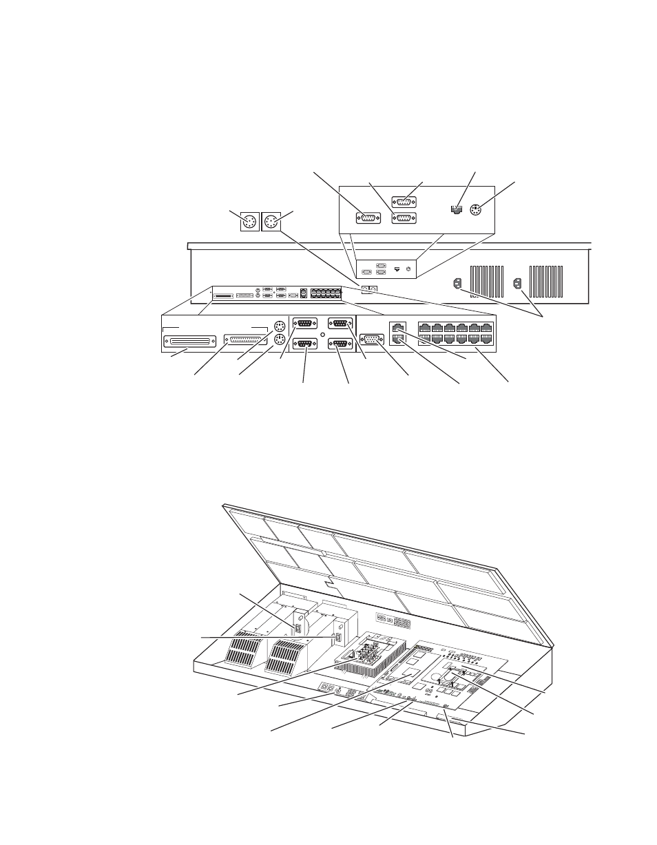
Early model 2-M/E Main panel rear connectors are shown in
modified for Enhanced Menu panel operation the indicated connectors are
inactive.
Figure 18. Early Model 2-M/E Main Panel, Rear View
Early model Kalypso 2-M/E Main panel power switches, reset buttons,
floppy drive, and circuit boards (including the Local Aux panel) are shown
in (
). Modified panels have unnecessary hardware removed.
Figure 19. Early Model 2-M/E Main Panel, Inside View
0618_06_93_r4
Menu Display Processor
Serial
Ports
Aux Panel
SCSI*
Parallel
Port*
Mouse*
Keyboard*
Menu
Touchscreen*
Diagnostic
Emergency
Bypass Mixer
Emergency
Bypass Router
Panel
Diagnostic
Panel
LAN
Menu Display
SVGA Video Out*
Satellite Control
Panels (12)
* Inactive on
modified systems.
Menu Panel
Power
Local Aux Bus
Power
Facility
LAN*
Menu
Controls*
AC In
LAN
Redundant
DC Power In
Menu
Diagnostic*
0618_06_94_r4
SATELLITE
PORTS
TRANSM
IT
RECEIVE
8 8 8
8 8 8
8 8
TRANSM
IT
GP8
GP7
GP6
GP5
GENERAL
PURPOSE
LEDS
GP4
GP5
GP1
GP0
RECEIVE
SATELL
ITE PO
RTS
FAULT
INIT
RUN
XMT
C119
RCV
LINK
RTP/CO
NTROL
PANEL
LAN
ACTIVIT
Y
COLN
C29
3.3V
R151
R152
POWER
SUPPL
IES
MENU
PROCE
SSOR
RESET
R153
5V
12V
SCSI
HARD
DISK
5 6
7
8
9
0
1
2
34
Primary
Power Supply
On/Off Switch
Redundant
Power Supply
On/Off Switch
Power Distribution
Board
Real Time (RT)
Processor
Floppy
Disk Drive
Menu (NT)
Processor
NT Hard Drive
Local Aux
Reset Button
Main Panel
Reset Button
Main Panel
Boot Dial Switch
Menu Panel Reset Button
- Kalypso User Manual V.12.0 Apr 10 2007 Kalypso Reference Manual V.11.0 Kalypso Reference Manual V.12.0 Mar 16 2006 Kalypso Reference Manual V.12.0 Apr 10 2007 Kalypso Classic Installation V.11.0 Kalypso Classic Installation V.12.0 Mar 13 2006 Kalypso Classic Installation V.12.0 Apr 10 2007 Kalypso User Manual V.11.0 Kalypso User Manual V.12.0 Mar 16 2006 Kalypso Reference Manual V.15.1 Kalypso User Manual V.15.1 HD/Duo Kalypso Installation V.15.0 HD/Duo Kalypso Installation V.11.0 HD/Duo Kalypso Installation V.15.1 Kalypso Reference Manual V.15.0 Video Switcher