Grass Valley Kalypso User Manual V.15.0 User Manual
Page 56
56
Kalypso — User Manual
Section 1 — System Overview
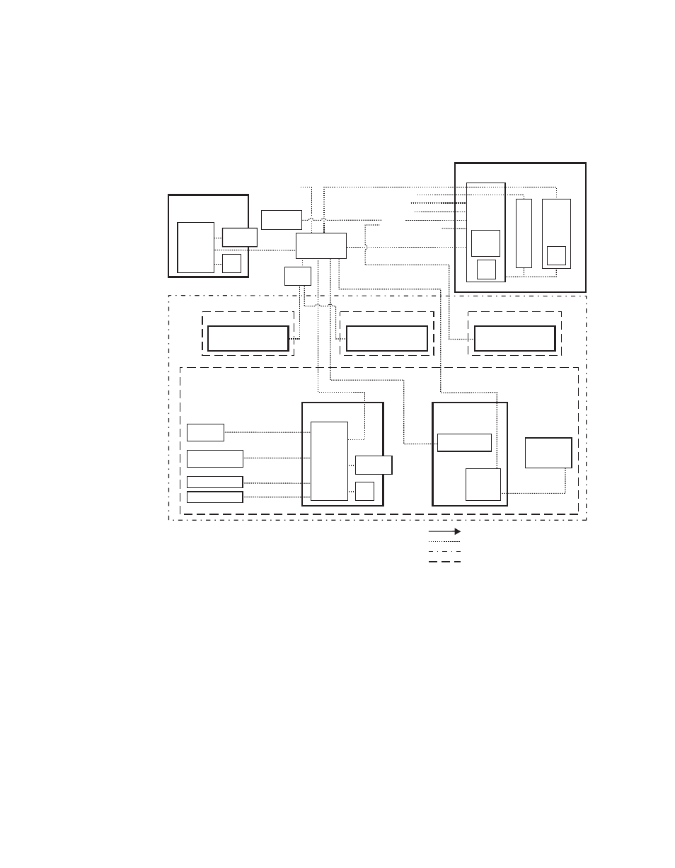
Late model 2-M/E Kalypso system control is the same as the 4-M/E
Kalypso system, except the Local Aux panel is built into the 2-M/E Main
panel (
Figure 43. Late Model 2-M/E Kalypso Control
Internal Control
Still Store LAN
Facility LAN
16 GPI In
16 GPI Out
8 Serial
Tally (Relay)
Kalypso Video Processor Frame
2 Synchronous Serial
Con
tr
ol
Sys
tem
Boot
Config BU
Flash
Tally
Hard
Drive
S
till S
to
re
Hard
Drive
Remote Control Surface #3
24-Crosspoint
Remote Aux Panel
32-Crosspoint
Remote Aux Panel
32-Crosspoint
Remote Aux Panel
To networked
image sources
LAN
Ethernet
Switch
Ethernet
Hub
0721_02_05_
r6
Remote Control Surface #1
Remote Control Surface #2
Kalypso Suite (Four Control Surfaces)
Shot Box
Facility LAN
Facility LAN
Video or Key Signal
Control Line
Suite Boundary
Control Surface Boundary
USB
USB
NOTES:
Control Panel, Facility, Still Store LAN: 10Base-T or 100Base-T Ethernet
Remote Aux Panels and Still Store are system options.
Point to Point Serial
Ports 1-12
RS-422/Serial Async
Main Control Surface
(Provided with Flush
Mount bracket.)
2-M/E
Main Panel
Menu Panel
Hard
Drive
CD-ROM
Drive
Optional Keyboard
Optional Mouse
Zip Drive
Menu
System
Processor
(Win 2000)
Optional CD-ROM
Real Time
Processor
Optional
Future Satellite
Panels (1-12)
Local Aux Panel
Additional
Menu Panel
(option)
Hard
Drive
CD-ROM
Drive
Menu
System
Processor
(Win 2000)
- Kalypso User Manual V.12.0 Apr 10 2007 Kalypso Reference Manual V.11.0 Kalypso Reference Manual V.12.0 Mar 16 2006 Kalypso Reference Manual V.12.0 Apr 10 2007 Kalypso Classic Installation V.11.0 Kalypso Classic Installation V.12.0 Mar 13 2006 Kalypso Classic Installation V.12.0 Apr 10 2007 Kalypso User Manual V.11.0 Kalypso User Manual V.12.0 Mar 16 2006 Kalypso Reference Manual V.15.1 Kalypso User Manual V.15.1 HD/Duo Kalypso Installation V.15.0 HD/Duo Kalypso Installation V.11.0 HD/Duo Kalypso Installation V.15.1 Kalypso Reference Manual V.15.0 Video Switcher