Grass Valley Kalypso User Manual V.15.0 User Manual
Page 36
36
Kalypso — User Manual
Section 1 — System Overview
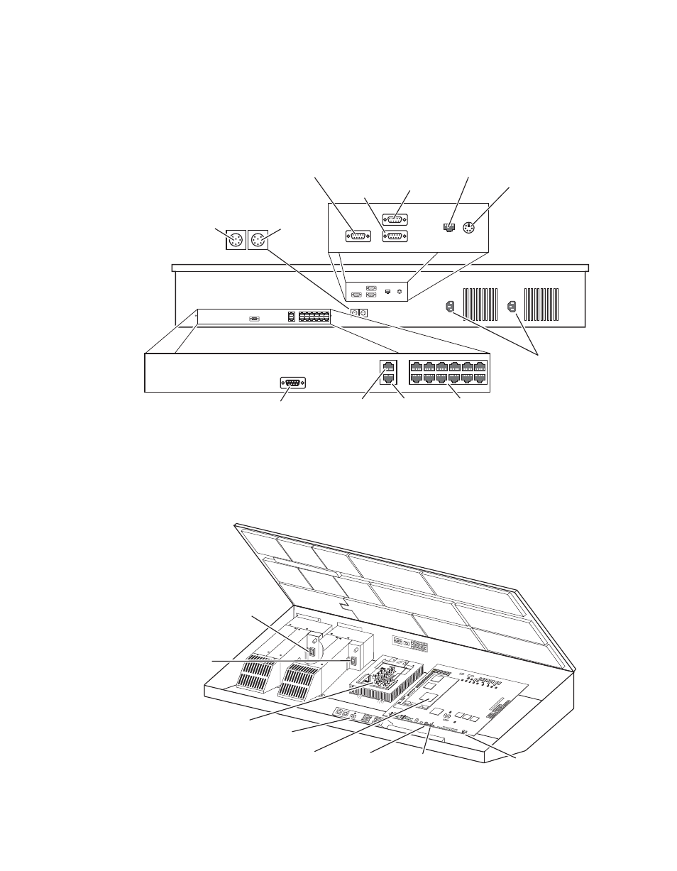
Late model Kalypso 2-M/E Main panels have connectors at the rear that are
identical to those on a late model 4-M/E system, except there are additional
Local Aux panel connections (
Figure 16. Late Model 2-M/E Main Panel, Rear View
The late model Kalypso 2-M/E Main panel power switches, reset buttons,
and circuit boards (including the Local Aux panel) are accessed by lifting
the top of the Main panel (
).
Figure 17. Late Model 2-M/E Main Panel, Inside View
8162_00_04_r0
Aux Panel
Diagnostic
Emergency
Bypass
Mixer
Emergency
Bypass
Router
Menu Panel
Power
Local Aux Bus
Power
AC In
LAN
Redundant
DC Power In
Panel
Diagnostic
Panel
LAN
Satellite Control
Panels (12)
Not
Used
0618_06_141_r0
SATELLITE
PORTS
TRANSM
IT
RECEIVE
8 8 8
8 8 8
8 8
TRANSM
IT
GP8
GP7
GP6
GP5
GENERAL
PURPOSE
LEDS
GP4
GP5
GP1
GP0
RECEIVE
SATELL
ITE PO
RTS
FAULT
INIT
RUN
XMT
C119
RCV
LINK
RTP/CO
NTROL
PANEL
LAN
ACTIVIT
Y
COLN
C29
3.3V
R151
R152
POWER
SUPPL
IES
MENU
PROCE
SSOR
RESET
R153
5V
12V
SCSI
HARD
DISK
5 6
7
8
9
0
1
2
34
Primary
Power Supply
On/Off Switch
Redundant
Power Supply
On/Off Switch
Power Distribution
Board
Real Time (RT)
Processor
Local Aux
Reset Button
Main Panel
Reset Button
Main Panel
Boot Dial Switch
Menu Panel
Reset Button (inactive)
- Kalypso User Manual V.12.0 Apr 10 2007 Kalypso Reference Manual V.11.0 Kalypso Reference Manual V.12.0 Mar 16 2006 Kalypso Reference Manual V.12.0 Apr 10 2007 Kalypso Classic Installation V.11.0 Kalypso Classic Installation V.12.0 Mar 13 2006 Kalypso Classic Installation V.12.0 Apr 10 2007 Kalypso User Manual V.11.0 Kalypso User Manual V.12.0 Mar 16 2006 Kalypso Reference Manual V.15.1 Kalypso User Manual V.15.1 HD/Duo Kalypso Installation V.15.0 HD/Duo Kalypso Installation V.11.0 HD/Duo Kalypso Installation V.15.1 Kalypso Reference Manual V.15.0 Video Switcher