Figure 119 – Grass Valley Kalypso User Manual V.15.0 User Manual
Page 139
Kalypso — User Manual
139
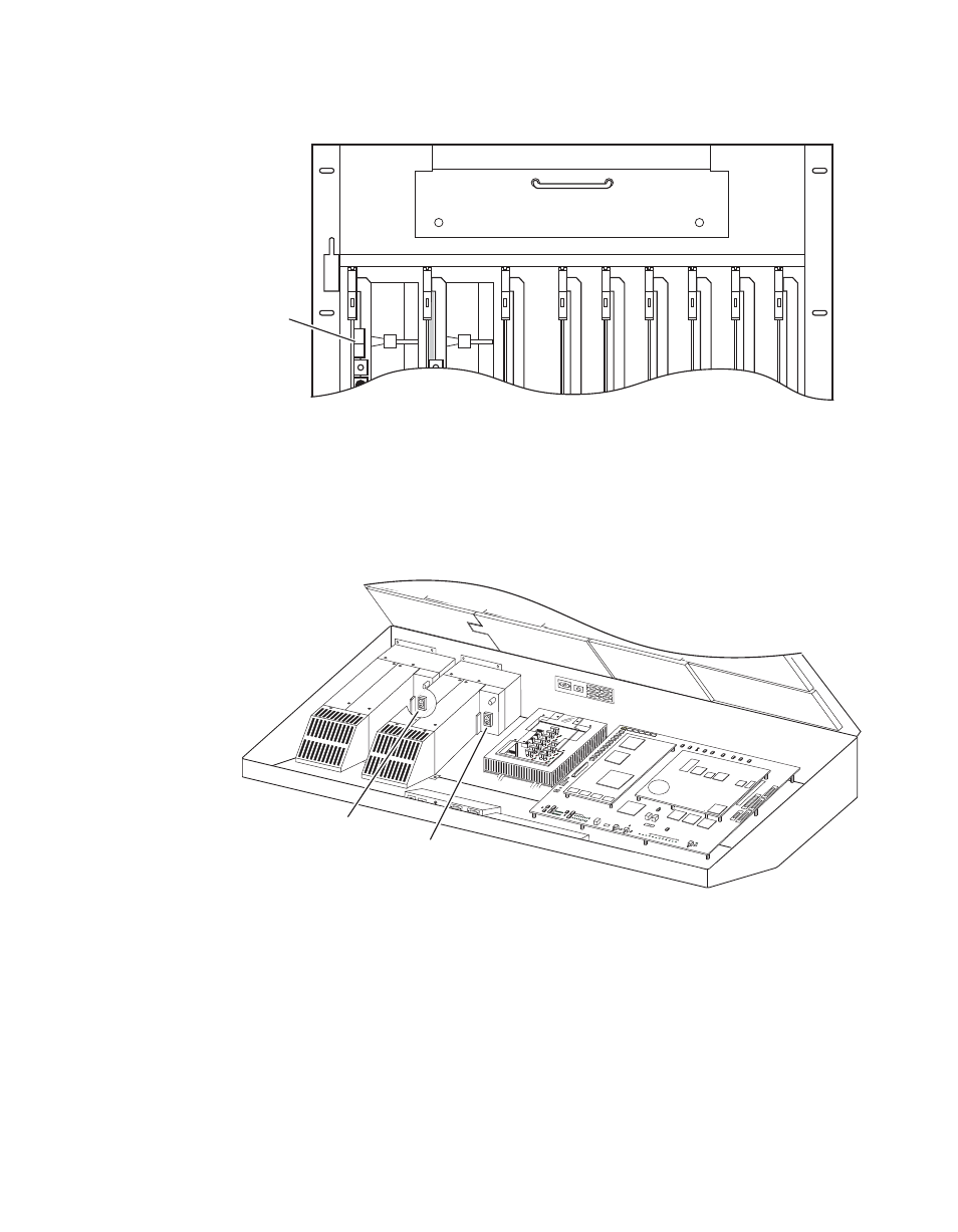
Power Up
Figure 119. Kalypso HD/Duo Video Processor Frame, Front View, Door Open
CAUTION The front door of the Kalypso Video Processor must remain closed during
normal system operation for proper cooling airflow.
3.
Set the power switch(es) in the Main Panel tub enclosure to On
(
).
Figure 120. Main Panel, Lid Open
When the Kalypso system powers up or is reset, the first system elements
activated are the PGM PST buses, transition, and keying controls. This
permits rapid on-air recovery of basic system operations. Sources can be
cut, mixed, and wiped, and keys can be placed on and off air while the rest
of the system initializes. The Menu panel system is the last item to initialize
after system power up. When the system is completely ready for operation
the Menu panel will display a Kalypso menu and the Main panel and Local
Aux panels will report sources on their Source Name displays.
0618_08_01_r1
OFF
ON
Kalypso HD
Video Processor Frame
Power Switch
0646_06_73_
r0
SATELLITE
PORTS
TRANSM
IT
RECEIVE
8 8 8
8 8 8
8 8
TRANSM
IT
GP8
GP7
GP6
GP5
GENERAL
PURPOSE
LEDS
GP4
GP5
GP1
GP0
RECEIVE
SATELL
ITE PO
RTS
FAULT
INIT
RUN
XMT
C119
RCV
LINK
RTP/CO
NTROL
PANEL
LAN
ACTIVIT
Y
COLN
C29
3.3V
R151
R152
POWER
SUPPL
IES
MENU
PROCE
SSOR
RESET
R153
5V
12V
SCSI
HARD
DISK
5 6
7
8
9
0
1
2
34
Primary
Power Supply
Switch
Redundant
Power Supply
Switch
- Kalypso User Manual V.12.0 Apr 10 2007 Kalypso Reference Manual V.11.0 Kalypso Reference Manual V.12.0 Mar 16 2006 Kalypso Reference Manual V.12.0 Apr 10 2007 Kalypso Classic Installation V.11.0 Kalypso Classic Installation V.12.0 Mar 13 2006 Kalypso Classic Installation V.12.0 Apr 10 2007 Kalypso User Manual V.11.0 Kalypso User Manual V.12.0 Mar 16 2006 Kalypso Reference Manual V.15.1 Kalypso User Manual V.15.1 HD/Duo Kalypso Installation V.15.0 HD/Duo Kalypso Installation V.11.0 HD/Duo Kalypso Installation V.15.1 Kalypso Reference Manual V.15.0 Video Switcher