Grass Valley Kalypso User Manual V.15.0 User Manual
Page 44
44
Kalypso — User Manual
Section 1 — System Overview
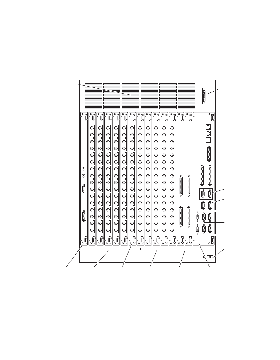
The rear bay holds input and output modules and provides reference and
system control connections. A fully loaded system is shown in
Some of the modules illustrated are optional and may not be included in
your Kalypso system. The slots on the rear of the Video Processor frame are
numbered from right to left.
Figure 32. Fully Equipped Kalypso Classic Video Processor Frame, Rear View
The Kalypso system has been designed for easy maintenance. All modules
of the same type are identical, and can be swapped with one another.
Modules can be removed and replaced safely with the power on, simpli-
fying troubleshooting to the module level.
J4
J3
TIMECODE IN
J2
J1
REFERENCE
REFERENCE
IN
OUT
IN
J6
J4
J5
J8
J7
J10
J9
2
1
J13
J12
5
4
J16
J15
8
J11
3
J14
6
7
422/
CPL
SERIAL
PORTS
GPI
COMM 1
COMM I/O
CONTROL
PANEL
LAN
J1
FACILITY
LAN
J2
STILL
STORE
LAN
J3
SERIAL
OUTPUT
J1
J2
J3
J4
J5
J6
J7
J8
J9
J10
J11
J12
J13
J14
J15
J16
SERIAL
OUTPUT
J1
J2
J3
J4
J5
J6
J7
J8
J9
J10
J11
J12
J13
J14
J15
J16
SERIAL
OUTPUT
J1
J2
J3
J4
J5
J6
J7
J8
J9
J10
J11
J12
J13
J14
J15
J16
SERIAL
OUTPUT
J1
J2
J3
J4
J5
J6
J7
J8
J9
J10
J11
J12
J13
J14
J15
J16
SERIAL
OUTPUT
J1
J2
J3
J4
J5
J6
J7
J8
J9
J10
J11
J12
J13
J14
J15
J16
SERIAL
INPUT
J1
J2
J3
J4
J5
J6
J7
J8
J9
J10
J11
J12
J13
J14
J15
J16
SERIAL
INPUT
J1
J2
J3
J4
J5
J6
J7
J8
J9
J10
J11
J12
J13
J14
J15
J16
SERIAL
INPUT
J1
J2
J3
J4
J5
J6
J7
J8
J9
J10
J11
J12
J13
J14
J15
J16
SERIAL
INPUT
J1
J2
J3
J4
J5
J6
J7
J8
J9
J10
J11
J12
J13
J14
J15
J16
EFFECTS
SEND
J1
J2
J3
J4
J5
J6
J7
J8
J9
J10
J11
J12
J13
J14
J15
J16
1A
1B
2A
2B
3A
3B
4A
4B
SERIAL
INPUT
J1
J2
J3
J4
J5
J6
J7
J8
J9
J10
J11
J12
J13
J14
J15
J16
TALLY
J1
J2
TALLY
J1
J2
J1
DC
INPUT
J3
TIMECODE
IN
J4
ALARM
Slot B17
Reference In
Module
Slots B16-B12
Output Modules (5)
(optional)
Slots B10-B6
Input Modules (5)
(1 standard [B10],
4 optional)
Slots B5-B4
Tally Modules (2)
(1 standard [B5],
1 optional)
Slot B1
Control I/O Module
(3 slots wide)
Slot B11
Effects Send
Module
Air Exhaust
DC Input from
Power Supply
0619_00_05_
r9
Chassis
Grounding
Lug
CPL
Peripheral
Bus II
Editor
Tally
Remote
Aux Panels
- Kalypso User Manual V.12.0 Apr 10 2007 Kalypso Reference Manual V.11.0 Kalypso Reference Manual V.12.0 Mar 16 2006 Kalypso Reference Manual V.12.0 Apr 10 2007 Kalypso Classic Installation V.11.0 Kalypso Classic Installation V.12.0 Mar 13 2006 Kalypso Classic Installation V.12.0 Apr 10 2007 Kalypso User Manual V.11.0 Kalypso User Manual V.12.0 Mar 16 2006 Kalypso Reference Manual V.15.1 Kalypso User Manual V.15.1 HD/Duo Kalypso Installation V.15.0 HD/Duo Kalypso Installation V.11.0 HD/Duo Kalypso Installation V.15.1 Kalypso Reference Manual V.15.0 Video Switcher