Kalypso — user manual 33 system components, Figure 13. kalypso local aux panel – Grass Valley Kalypso User Manual V.15.0 User Manual
Page 33
Kalypso — User Manual
33
System Components
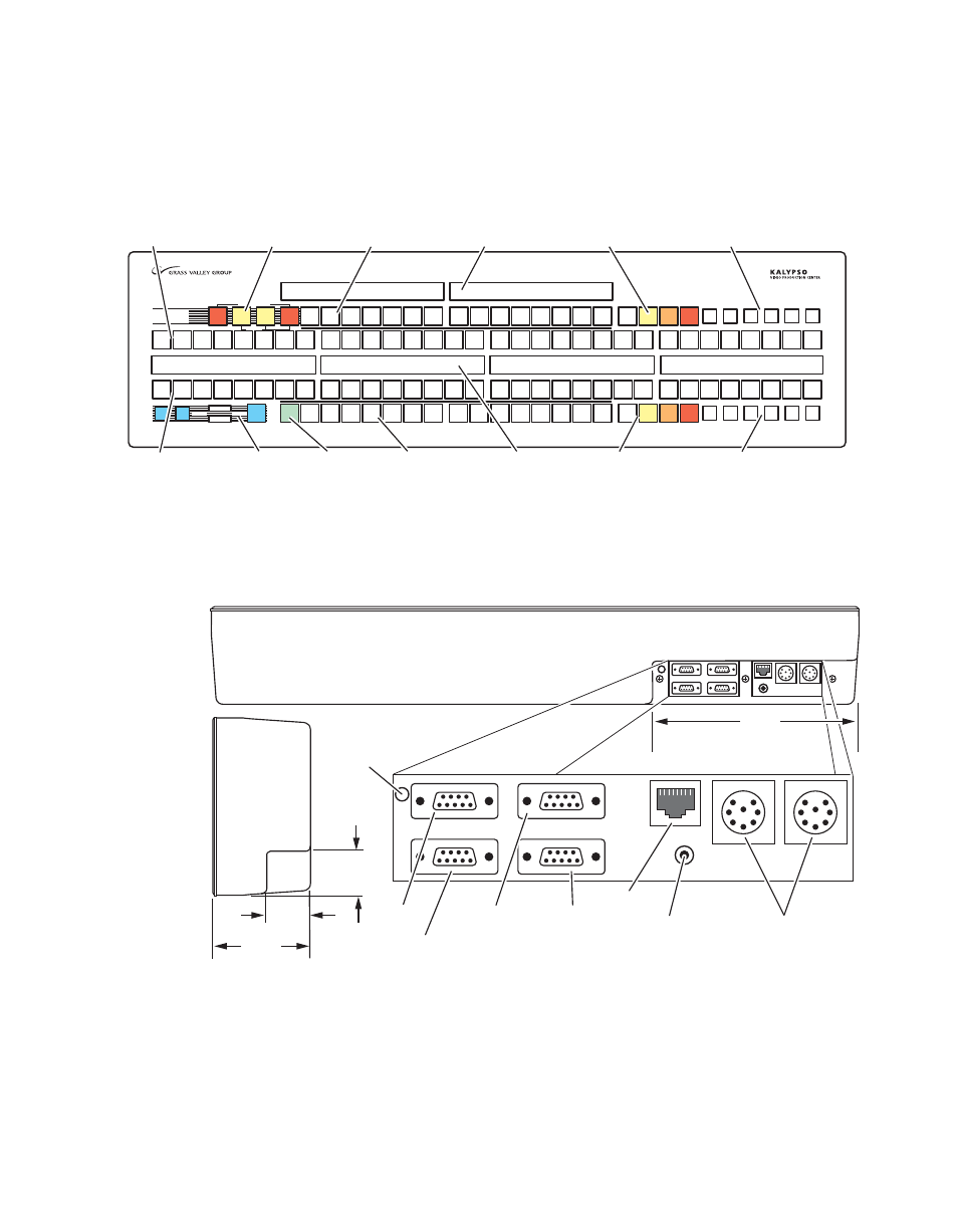
Router source selection and Emergency Bypass option operation
(
Figure 13. Kalypso Local Aux Panel
Connections to the Kalypso Main panel are located on the bottom of the
Local Aux panel (
).
Figure 14. Local Aux Panel, Bottom View of Connectors
The Local Aux panel is generally installed directly above the left side of the
Main panel so the Source Select buttons are aligned, though it can be
mounted in any convenient location.
Bypass Active
Assign
Emergency
Bypass
Select
Source
Key
Key
1
Key
Key
2
Aux
Aux
1
Aux
Aux
2
Aux
Aux
3
Aux
Aux
4
Aux
Aux
5
Aux
Aux
6
Aux
Aux
7
Bypass
Bypass
Deleg
Deleg
Bypass
Bypass
Enable
Enable
Switcher
Router
Router
Router
Assign
Assign
Next
Next
Page
Page
Prev
Prev
Page
Page
Gang
Gang
Select
Select
Aux
Aux
1
Aux
Aux
2
Aux
Aux
3
Aux
Aux
4
Aux
Aux
5
Aux
Aux
6
Aux
Aux
7
Aux
Aux
8
Aux
Aux
9
Aux
Aux
10
10
Aux
Aux
11
11
Aux
Aux
12
12
Still
Still
Store
Store
Aux
Aux
13
13
PVW
PVW
Pri
Pri
M/E
1
M/E
2
M/E
3
Pgm
Pgm
Pst
Pst
Shift
Shift
Un-
Un-
Shift
Shift
Hold
Hold
Near
Near
Side
Side
Far
Far
Side
Side
Key
Key
Split
Split
Aux
Aux
8
Aux
Aux
9
Aux
Aux
10
10
Aux
Aux
11
11
Aux
Aux
12
12
Still
Still
Store
Store
Aux
Aux
13
13
PVW
PVW
Pri
Pri
M/E
1
M/E
2
M/E
3
Pgm
Pgm
Pst
Pst
Shift
Shift
Un-
Un-
Shift
Shift
Hold
Hold
Near
Near
Side
Side
Key
Key
Split
Split
Far
Far
Side
Side
Source Name
Display (4 segments)
Router
Assignment (3)
Source Select
Bus #2 (32)
Source Select Modifiers (6)
for Bus #2
Aux Bus Status
Display (2 segments)
Emergency Bypass (4)
(option)
Source Select
Bus #1 (32)
Bus #1
Delegation (15)
Bus #2
Delegation (15)
Gang Select
Button
M/E Select
Bus #2 (4)
M/E Select
Bus #2 (4)
Source Select Modifiers (6)
for Bus #1
0618_02_19_r0
1.8 in.
46 mm
1.8 in.
46 mm
3.9 in.
99 mm
8.4 in.
213 mm
Bottom
View
Side
View
Without
Mounting
Bracket
Spare
Emergency
Bypass
Mixer
Diagnostic
Emergency
Bypass
Router
LAN
0618_03_127_
r2
Main and Redundant
DC Power In
Local Aux Panel
Boot Dial
(recessed)
Local Aux Panel
Reset Button
- Kalypso User Manual V.12.0 Apr 10 2007 Kalypso Reference Manual V.11.0 Kalypso Reference Manual V.12.0 Mar 16 2006 Kalypso Reference Manual V.12.0 Apr 10 2007 Kalypso Classic Installation V.11.0 Kalypso Classic Installation V.12.0 Mar 13 2006 Kalypso Classic Installation V.12.0 Apr 10 2007 Kalypso User Manual V.11.0 Kalypso User Manual V.12.0 Mar 16 2006 Kalypso Reference Manual V.15.1 Kalypso User Manual V.15.1 HD/Duo Kalypso Installation V.15.0 HD/Duo Kalypso Installation V.11.0 HD/Duo Kalypso Installation V.15.1 Kalypso Reference Manual V.15.0 Video Switcher