Grass Valley Kalypso User Manual V.15.0 User Manual
Page 28
28
Kalypso — User Manual
Section 1 — System Overview
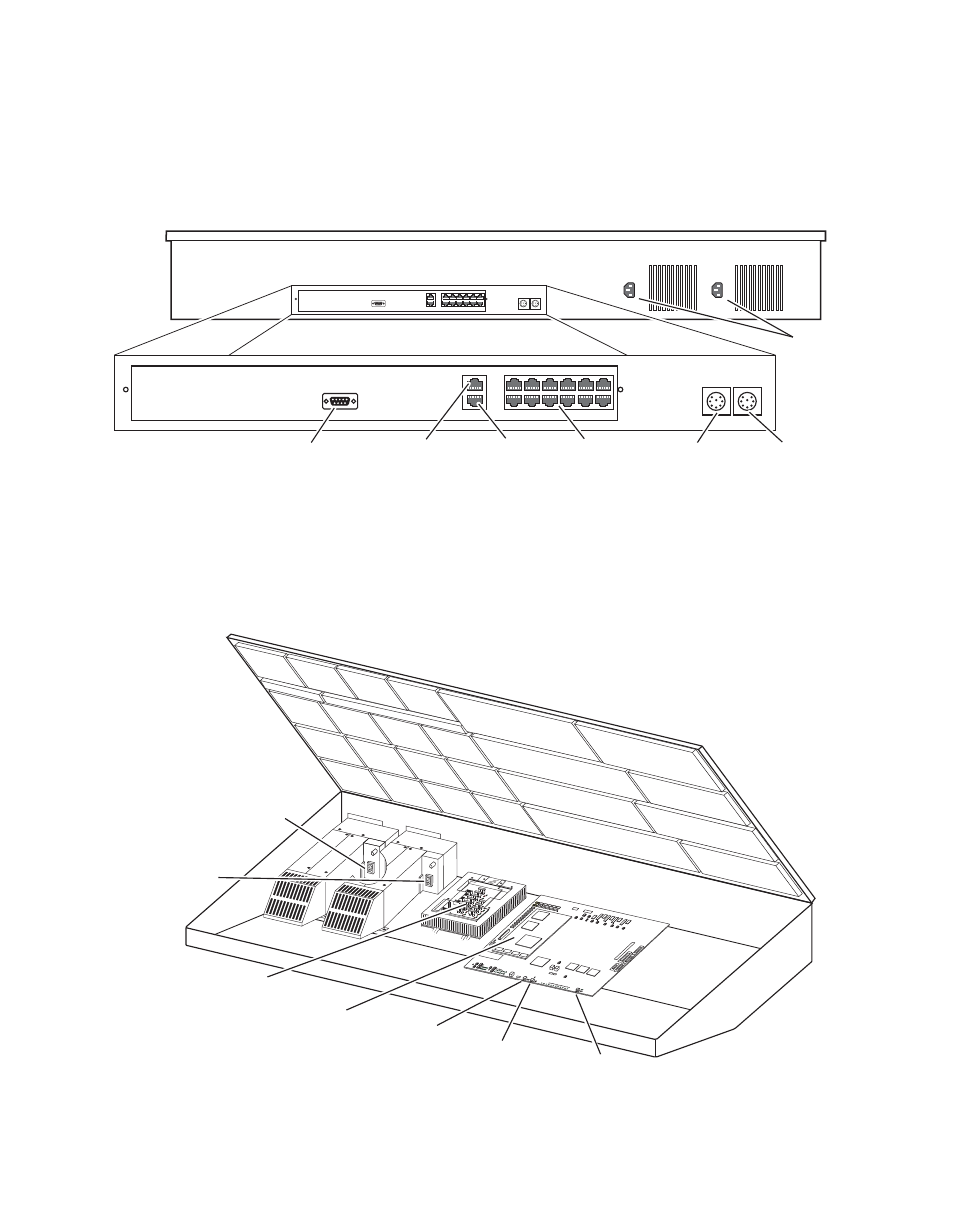
Two models of 4-M/E Main panel exist. Late model designs shipping at the
time of this manual’s publication have the connections shown in
This model Main panel works with the Enhanced Menu panel.
Figure 4. Late Model 4-M/E Main Panel, Rear View
Main panel power switches and the Main panel reset button are accessed
by lifting the top of the Main panel (
). A redundant power supply
can be installed into the tub of the Main panel as an option. The Main panel
provides power to the separate Menu panel and Local Aux panel.
Figure 5. Late Model 4-M/E Main Panel Inside View
Menu Panel
Power
Local Aux Bus
Power
Panel
Diagnostic
Panel
LAN
Satellite Control
Panels (12)
Not
Used
AC In
8162_00_02_
r0
0618_06_140_r0
SATELLITE POR
TS
TRANSMIT
RECEIVE
8 8 8
8 8 8
8 8
TRANSMIT
GP8
GP7
GP6
GP5
GENE
RAL
PURPOSE
LEDS
GP4
GP5
GP1
GP0
RECEIVE
SATELLI
TE P
ORTS
FAULT
INIT
RUN
XMT
C119
RCV
LINK
RTP/CONTR
OL P
ANEL L
AN
ACT
IVITY
COL
N
C29
3.3V
R151
R152
POWE
R SUP
PLIES
MENU
PROCESSOR
RESE
T
R15
3
5V
12V
SCSI
HARD
DISK
5 6
7
8
9
0
1
2
34
Real Time (RT)
Processor
(with Disk on Chip)
Power Distribution
Board
Primary
Power Supply
On/Off Switch
Redundant
Power Supply
On/Off Switch
Main Panel
Reset Button
Menu Panel
Reset Button (inactive)
Main Panel
Boot Dial Switch
- Kalypso User Manual V.12.0 Apr 10 2007 Kalypso Reference Manual V.11.0 Kalypso Reference Manual V.12.0 Mar 16 2006 Kalypso Reference Manual V.12.0 Apr 10 2007 Kalypso Classic Installation V.11.0 Kalypso Classic Installation V.12.0 Mar 13 2006 Kalypso Classic Installation V.12.0 Apr 10 2007 Kalypso User Manual V.11.0 Kalypso User Manual V.12.0 Mar 16 2006 Kalypso Reference Manual V.15.1 Kalypso User Manual V.15.1 HD/Duo Kalypso Installation V.15.0 HD/Duo Kalypso Installation V.11.0 HD/Duo Kalypso Installation V.15.1 Kalypso Reference Manual V.15.0 Video Switcher