Configure a powermonitor wireless 250 device, Pc receiver connection, Rs-232 data port use and – Rockwell Automation Energy Management Accelerator Toolkit Quick Start User Manual
Page 67: Configuration, Configure a powermonitor, Wireless 250 device, Pc receiver rs-485 data port, Use and configuration
Rockwell Automation Publication IASIMP-QS016C-EN-P - October 2014
67
Energy Data Collector Configuration Chapter 3
Configure a PowerMonitor Wireless 250 Device
The PowerMonitor Wireless 250 monitors are factory configured. Each PowerMonitor Wireless 250 device is assigned a
Group ID and Device ID in the factory. These should not be modified except under exceptional circumstances. One such
circumstance would be operating two or more independent PowerMonitor W250 networks in such close proximity that
RF interference with each other occurs. Please contact Rockwell Automation support services for more information or if
assistance is required.
The PC Receiver can be configured for RS-232 or RS-485 data port use.
PC Receiver Connection
This section describes the RS-232 and RS-485 connections.
RS-232 Data Port Use and Configuration
DB-9 style connector: RS-232 Data Port connector with standard DCE connections for transmit data, receive data, RTS
input, and CTS output.
The PC Receiver is factory configured with the following parameters:
• Communication Rate - 115,200
• Data Bits - 8
• Parity - None
• Stop Bits - 1
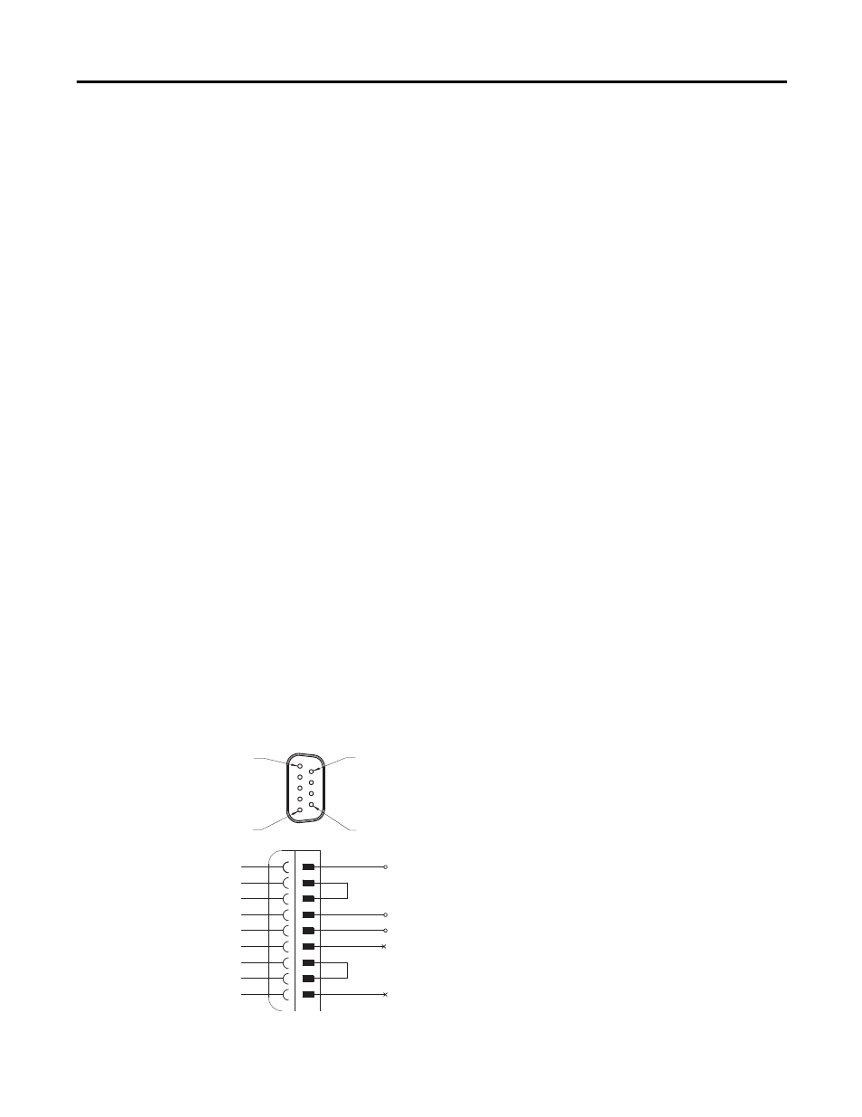
PC Receiver RS-485 Data Port Use and Configuration
The RS-485 mode of the PC Receiver requires special wiring for the DB9 connection. In order to activate the RS-485
mode, please connect the data port as follows.
PC Receiver RS-485 Wiring Diagram
1
5
9
6
1
2
3
4
5
6
7
8
9
Inverting Signal -
NC
GND
Non-inverting Signal +
NC