Rockwell Automation Energy Management Accelerator Toolkit Quick Start User Manual
Page 321
Rockwell Automation Publication IASIMP-QS016C-EN-P - October 2014
321
FactoryTalk View ME Energy Faceplates
Chapter 11
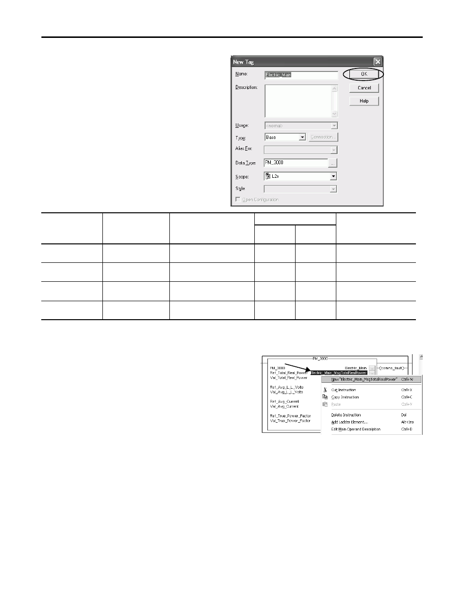
5. Click OK to accept the default setup for the new
PowerMonitor tag.
The PowerMonitor Add-On Instructions use
explicit messaging to retrieve data from
PowerMonitor devices. You must configure an
explicit message for each PowerMonitor data
address. Four messages will be configured to display
PowerMonitor device values on the Equipment
Status and Alarm History faceplates. The table lists
the data and corresponding Add-On Instruction
parameters, tags, and addresses to be configured for
each device.
6. Select the message tag name field next to the
Ref_Total_Real_Power parameter and type a tag name in the
format x
xx_MsgTotalRealPower.
For this example Electric_Main_MsgTotalRealPower is
entered.
7. Right-click the message tag name just entered and choose New
‘
xxx_MsgTotalRealPower’.
For this example, New ‘Electric_Main_MsgTotalRealPower’ is
selected.
Table 3 - PowerMonitor Add-On Instruction Tag References
PowerMonitor Data
Add-On Instruction
Parameter Tags
Message Tag
PLC5 Address
Message Destination Tag
PowerMonitor
1000
PowerMonitor
3000
Real Power
Ref_Total_Real_Power
Val_Total_Real_Power
xxx
(1)
_MsgTotalRealPower
(1) xxx is the PowerMonitor device name. For example, the prefix Electric_Main in Electric_Main_MsgTotalRealPower is the message tag for the PM 3000 Electric_Main device.
F22:7
F17:3
xxx
r
Average L-L Volts
Ref_Avg_L_L_Volts
Val_Avg_L_L_Volts
xxx
F21:11
F15:11
xxx
Average Current
Ref_Avg_Current
Val_Avg_Current
xxx
F21:3
F15:3
xxx
True Power Factor
Ref_True_Power_Factor
Val_True_Power_Factor
xxx
ctor
F22:3
F19:3
xxx
or