Editing tuning panels, Saving tuning panels – Yaskawa MP900 Series Machine Controller for Standard Operation User Manual
Page 463
Ladder Logic Programming
7.6.2 Creating Tuning Panels
7-96
7
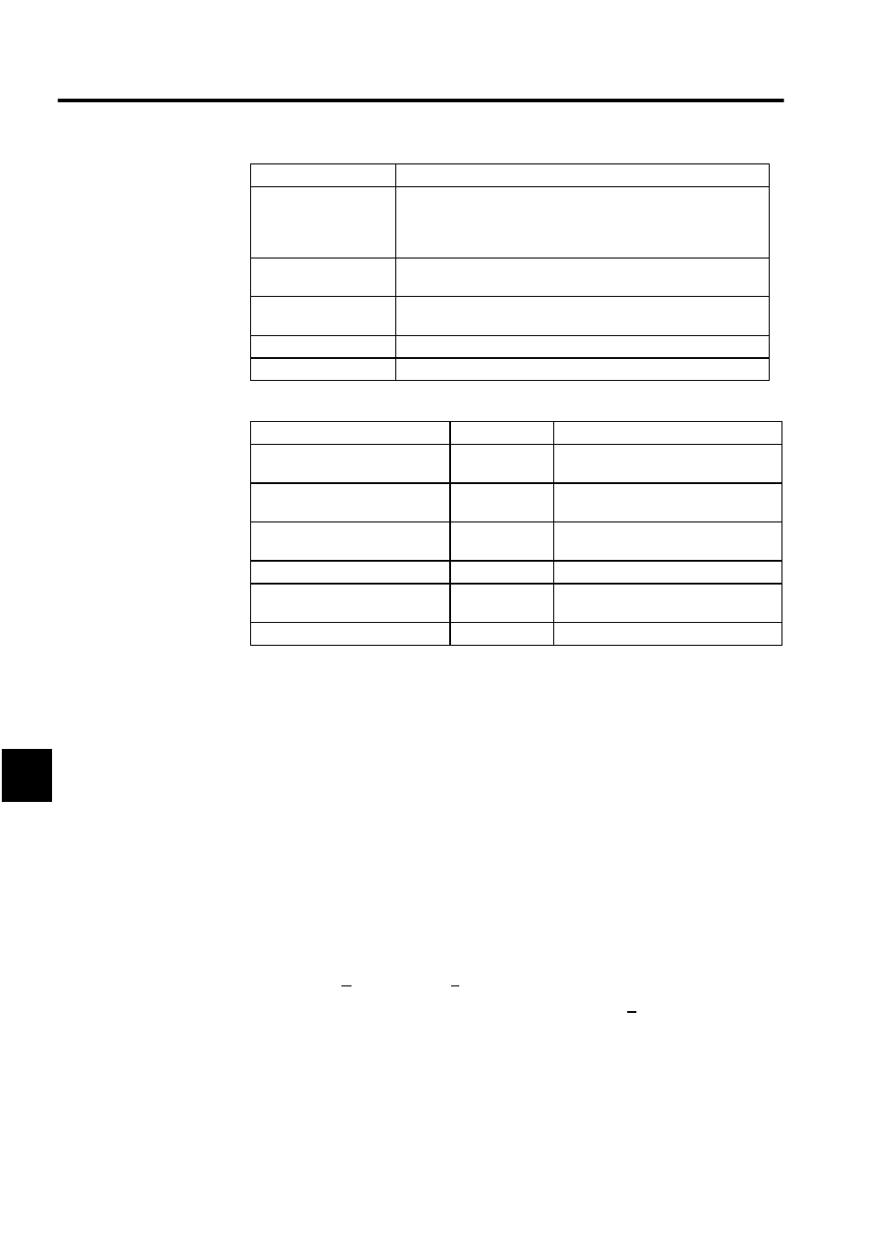
Table Formats
∗
Negative values cannot be input when the current values are input.
Note: The decimal point will move depending on the current value. If cur-
rent values have more digits than can be displayed, these values will
be converted to real numbers with exponents and displayed.
Editing Tuning Panels
The editing methods for tuning panels are the same as for table programs. Refer to 7.4.11
Editing Table Programs.
Saving Tuning Panels
If a program window for the same drawing number is opened, that program (main or other
program) will be saved also.
The procedure to save tuning panels is outlined below.
1. Select File (F) and then Save (S) on the Tuning Panel Menu.
2. The Save DWG/FUNC Window will be displayed. Click the Yes Button.
3. The Save Normally Completed Window will be displayed. Click the OK Button.
Upper Limit
Enter the upper limit for the current value. If the same value is set for
both the upper and lower limits, that value is the only current value
that can be entered. Enter upper and lower limits such that the lower
value is equal to or less than the upper limit.
REG-No.
Enter the register number for displaying the current value. I, O, M,
and D registers can be entered.
DWG
If a D register number is input in the REG-No. column, input the D
register drawing number.
DWG No.
Display the number of the drawing that is currently open.
Input Mode
Display the current input mode.
Current Value
Display Format
Register Type
Positive signed number
Xx.xxx
Position number, double-length positive
number
Positive unsigned number
Uxx.xxx
Position number, double-length positive
number*
Hexadecimal
Hxxxx
Position number, double-length positive
number*
Real number (with exponent)
x.xxxxxE.xx
Real number
Real number
(without exponent)
x.xxxxx
Real number
Bit signal
ON/OFF or 0/1
Bit*
Setting
Explanation