Yaskawa MP900 Series Machine Controller for Standard Operation User Manual
Page 219
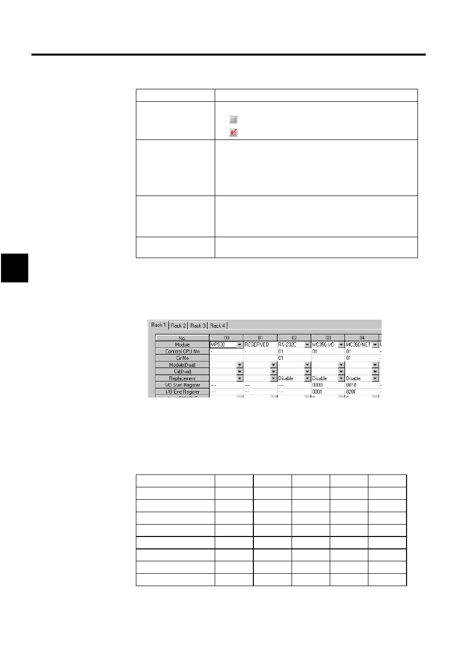
Module Configuration Definitions
3.6.7 MC350-NET Definitions
3-124
3
1. TYPE (MECHATROLINK Devices)
Refer to D.1 MECHATROLINK Devices for a list of the currently supported MECHA-
TROLINK Devices.
2. INPUT/OUTPUT SIZE
3. Automatic Input Register Allocation
When a SERVOPACK has been connected, the input registers are allocated automati-
cally as shown in the following table. These registers are allocated automatically only
when automatic PGM generation is set on the Group Definitions Window to enable
automatic ladder program generation.
D
Controls the output register's disable setting.
• :
Enabled
• :
Disabled
OUTPUT, SIZE
Sets the leading output register and number of registers (SIZE). The
number of registers is set automatically. Be sure that the range of
registers set for each station do not overlap with another station's
register numbers. The setting range for registers is determined by the
leading register number and ending register number set in the Mod-
ule Configuration Definitions Window.
SCAN
Sets the scan for I/O servicing. The scan will be fixed at “High”
when a SERVOPACK is set in the TYPE field.
• High: High-speed scan
• Low: Low-speed scan
Station Name
(Comment)
Comments up to 32 characters can be input for each station.
Axis Input Signals
Axis 01
Axis 02
Axis 03
...
Axis 04
Servo ON
IB00100
IB00110
IB00120
...
IB001D0
JOG+
IB00101
IB00111
IB00121
...
IB001D1
JOG-
IB00102
IB00112
IB00122
...
IB001D2
STEP+
IB00103
IB00113
IB00123
...
IB001D3
STEP-
IB00104
IB00113
IB00124
...
IB001D4
ZRN
IB00105
IB00115
IB00125
...
IB001D5
Zero Point Setting
IB00106
IB00116
IB00126
...
IB001D6
Stop
IB00107
IB00117
IB00127
...
IB001D7
Setting Item
Details