5 inputting # register constant table data, Switching cursor movement direction – Yaskawa MP900 Series Machine Controller for Standard Operation User Manual
Page 422
7.4 Creating Table Programs
7-55
7
Switching Cursor Movement Direction
Use the procedure to switch the cursor movement direction after table data has been entered
and the Enter Key pressed.
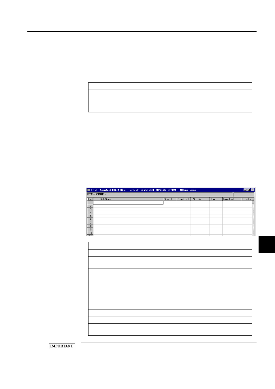
7.4.5 Inputting # Register Constant Table Data
# register constant tables are created by inputting constants (integer, double-length integer,
and real number constants), symbols, and # register numbers.
When a # register constant table is saved, the constants are automatically converted and the
results placed in the # registers after the upper and lower limits of each constant have been
checked.
Table data can be created for as many # registers as are set on the DWG Definition Tab Page
in the Property Window.
1 SETVAL, Upper Limit, Lower Limit, and Save Point must be set. An error will occur when the table is
Movement Direction
Details
Horizontal
Select Input (I) and then Direction of Cursor Movement (C) from
the menus. The Designate Direction of Cursor Movement Window
will be displayed. Specify the direction of movement and click the
OK Button.
Vertical
No movement
Setting Item
Details
Data Name
Enter constant names of up to 48 characters.
Symbol
Enter a symbol of up to 8 characters to be used for the destination #
register.
Save Point
Enter the # register number to which the constant will be saved.
SETVAL
Enter the constant to be saved to the # register. When inputting in
hexadecimal, add an "H" to the beginning of the value, such as
H00FF.
When inputting settings, input values within the range outlined in the
Lower Limit and Upper Limit columns. The settings will be checked
against these limits.
Unit
Enter a unit for the constant of up to 8 characters.
Lower Limit
Enter the lower limit of the constant.
Upper Limit
Enter the upper limit of the constant. The lower limit must be equal
to or less than the upper limit.