10 260if setup, Opening the 260if definitions window – Yaskawa MP900 Series Machine Controller for Standard Operation User Manual
Page 157
Module Configuration Definitions
3.5.10 260IF Setup
3-62
3
Saving, Deleting, and Closing 218IF Transmission Definitions Data
Refer to the procedures in 3.3 Basic Individual Module Definition Operations for details.
1 The connection parameters cannot be saved unless the parameter input values pass a consistency
check. See Connection Parameter Consistency Check on page 3-58 for details.
2 An Error Detection Message Box is displayed if the data was not saved successfully. Refer to Appendix
A Error Messages, eliminate the cause of the error, and save the data again.
3.5.10 260IF Setup
Perform the setup for the 260IF from the CP-717 Engineering Tool.
Opening the 260IF Definitions Window
The procedure to open the 260IF Definitions Window is given below.
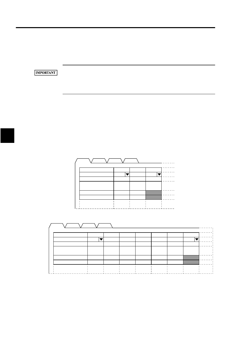
1. Double-click the Module configuration definitions set in the controller mounting the
260IF Module. The Module Configuration Definitions Window will be displayed.
Fig 3.10 MP920 Module Configurations Window
Fig 3.11 MP940 Module Configurations Window
With the MP920, select the 260IF Module for the 260IF Module mounting slot. In the
MP920 Module Configurations Window example shown above, 260IF has been allo-
cated to slot 02.
With the MP940, the 260IF is allocated to slot 06 and this cannot be changed; select the
No.
・
・
・
・
・
00
MP920
・・・
・・・
・・・
・・・
RESERVED
01
・・・
・・・
・・・
・・・
02
260IF
・・・
・・・
・・・
・・・
・・・
・・・
・・・
Rack 1
Module
Control CPU No.
I/O Start Register
I/O End Register
No.
・
・
・
・
・
00
MP920
・・・
・・・
・・・
・・・
RESERVED
01
・・・
・・・
・・・
・・・
06
260IF
・・・
・・・
・・・
・・・
・・・
・・・
・・・
SERIAL
02
・・・
・・・
・・・
・・・
LIO
03
・・・
・・・
・・・
・・・
SVA
04
・・・
・・・
・・・
・・・
CNTR
05
・・・
・・・
・・・
・・・
Rack 1
Module
Control CPU No.
I/O Start Register
I/O End Register