13 digital output definitions, Outline of the digital output definitions, Opening the digital output definitions window – Yaskawa MP900 Series Machine Controller for Standard Operation User Manual
Page 169

Module Configuration Definitions
3.5.13 Digital Output Definitions
3-74
3
Register allocations can be deleted for discrete inputs 1 to 4. When the register allocation for discrete
input 1 is deleted, the allocations for interrupt inputs 1 and 2 will be deleted simultaneously. When the
allocation for discrete input 2 is deleted, the allocations for interrupt inputs 3 and 4 will be deleted
simultaneously.
Saving, Deleting, and Closing Digital Input Definitions
Refer to the procedures in 3.3 Basic Individual Module Definition Operations for details.
3.5.13 Digital Output Definitions
This section explains how to set the Digital Output Definitions.
Outline of the Digital Output Definitions
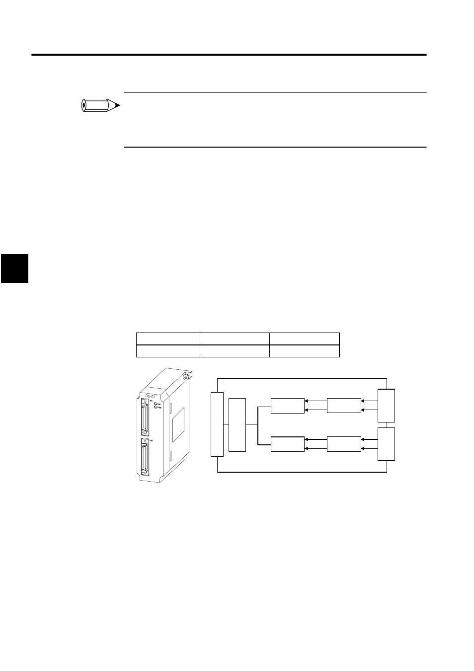
The DO-01 Module is equipped with 64 digital outputs (DO). Output servicing is performed
at fixed intervals, once for each scan (high-speed or low-speed) in the CPU-01 Module.
The Digital Output Definitions Window sets the scan timing and allocates registers to the
discrete outputs (32 each) in connectors CN1 and CN2.
Opening the Digital Output Definitions Window
Open the Digital Output Definitions Window according to the procedure in 3.3 Basic Indi-
vidual Module Definition Operations.
INFO
I/O Type
Connector CN1
Connector CN2
Discrete Output
32 outputs
32 outputs
32
CN1
32
CN1
Output
Port
S
yst
em Bus Connect
or
Sys
tem Bus
Interface
Output
Port
Isolated
DO
Isolated
DO
