Yaskawa MP900 Series Machine Controller for Standard Operation User Manual
Page 246
3.7 MP940 Module Definitions
3-151
3
2. IN Data
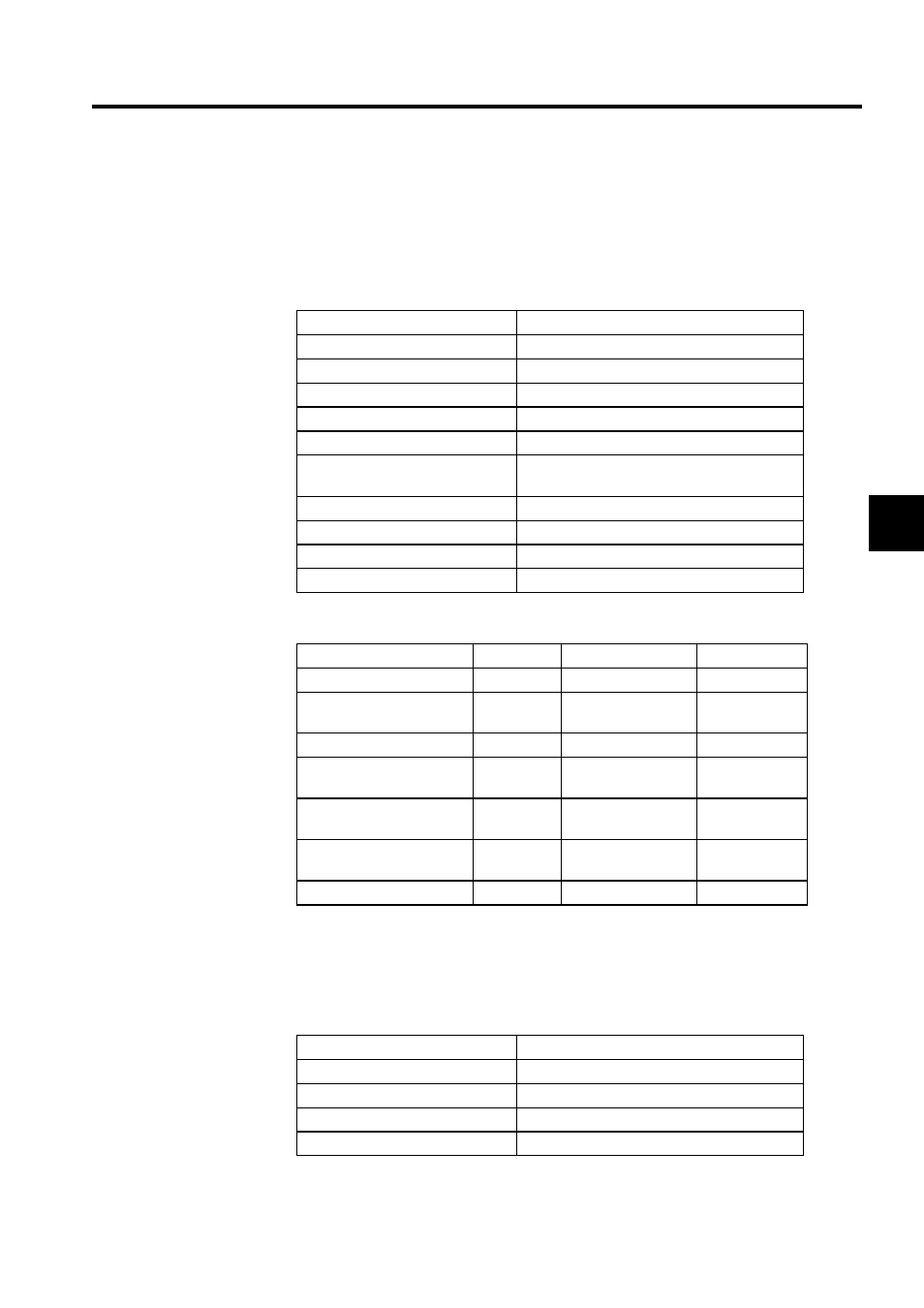
a) Status
Displays the status of each bit in the operating status register. The corresponding box
will contain a black circle when the bit is ON and a white circle when the bit is OFF.
The leading input register is the status word.
b) IN Data Settings
3. OUT Data
a) Operation Mode
The status of each bit of the output mode register is displayed. Settings can be
selected with option buttons.
Status
Meaning
Data Setting Error
ON: Data setting error
Fixed Data Setting Error
ON: Fixed parameter setting error
Count Value Preset
ON: Count value preset completed.
PI Latch Detected
ON: PI latch detection completed.
A/B Pulse 0
ON: Feedback pulses within ±1 pulse
Coincident Detection Signal
ON: Coincident detected signal ON (pulse
units).
Writing Fixed Parameter Now
ON: Parameters being written online.
A-pulse disconnect indication
ON: Disconnected.
B-pulse disconnect indication
ON: Disconnected.
Module Ready
ON: CNTR Module is ready.
Setting Item
Register
Range
Meaning
Increment Pulse
IL0004
0 to 2147483647
1 = 1 pulse
Hardware Counter Current
Value
IL0006
0 to 2147483647
1 = 1 pulse
PI Latch Data
IL0008
0 to 2147483647
1 = 1 pulse
After Convert Increment
Pulse
IL000A
0 to 2147483647
1 = 1 reference
unit
Counter Current Value
IL000C
0 to 2147483647
1 = 1 reference
unit
After Convert PI Latch
Data
IL000E
0 to 2147483647
-
System Monitor
IL0010
0 to 2147483647
-
Status
Meaning
Count
Enabled/Disabled
Count Value
Do/Don’t
PI Latch
Do/Don’t
Candescent
Do/Don’t