Yaskawa MP900 Series Machine Controller for Standard Operation User Manual
Page 255
Module Configuration Definitions
3.7.11 260IF Setup
3-160
3
Refer to 4.2 Calculating Communications Cycle Times in the MP920 Machine Control-
ler User's Manual: 260IF DeviceNet (SIEZ-C887-5.2) for details.
2. I/O Allocation Settings
The asterisks ("**") displayed on the left of the I/O allocations setting table denote the 260IF
itself, allocated using the Module configuration definitions.
Communications Cycle
Time (Maximum
Value); Display Only
Displays the communications cycle maximum value during I/O
transmission.
Setting Item
Details
Master/Slave
Set the operating mode (i.e., DeviceNet master or slave) for the 260IF.
Set to the same value as the value set using 260IF setting switch SW1
(X1).
MAC ID
The MAC ID is the DeviceNet MAC ID (i.e., DeviceNet address) of
the 260IF. Set to the same value as the value set using 260IF setting
switches SW2 and SW3.
MAC ID Field
The MAC ID field is the DeviceNet MAC ID (i.e., DeviceNet address)
for I/O allocation. MAC ID fields are set automatically in order start-
ing from 00.
D
Input enable/disable sets whether or not the Controller CPU exchanges
I/O data with the 260IF. Select it to disable I/O data exchange.
INPUT
Set the leading address of the input area (input register IWxxxx) allo-
cated to the relevant device. Specify using a hexadecimal word
address.
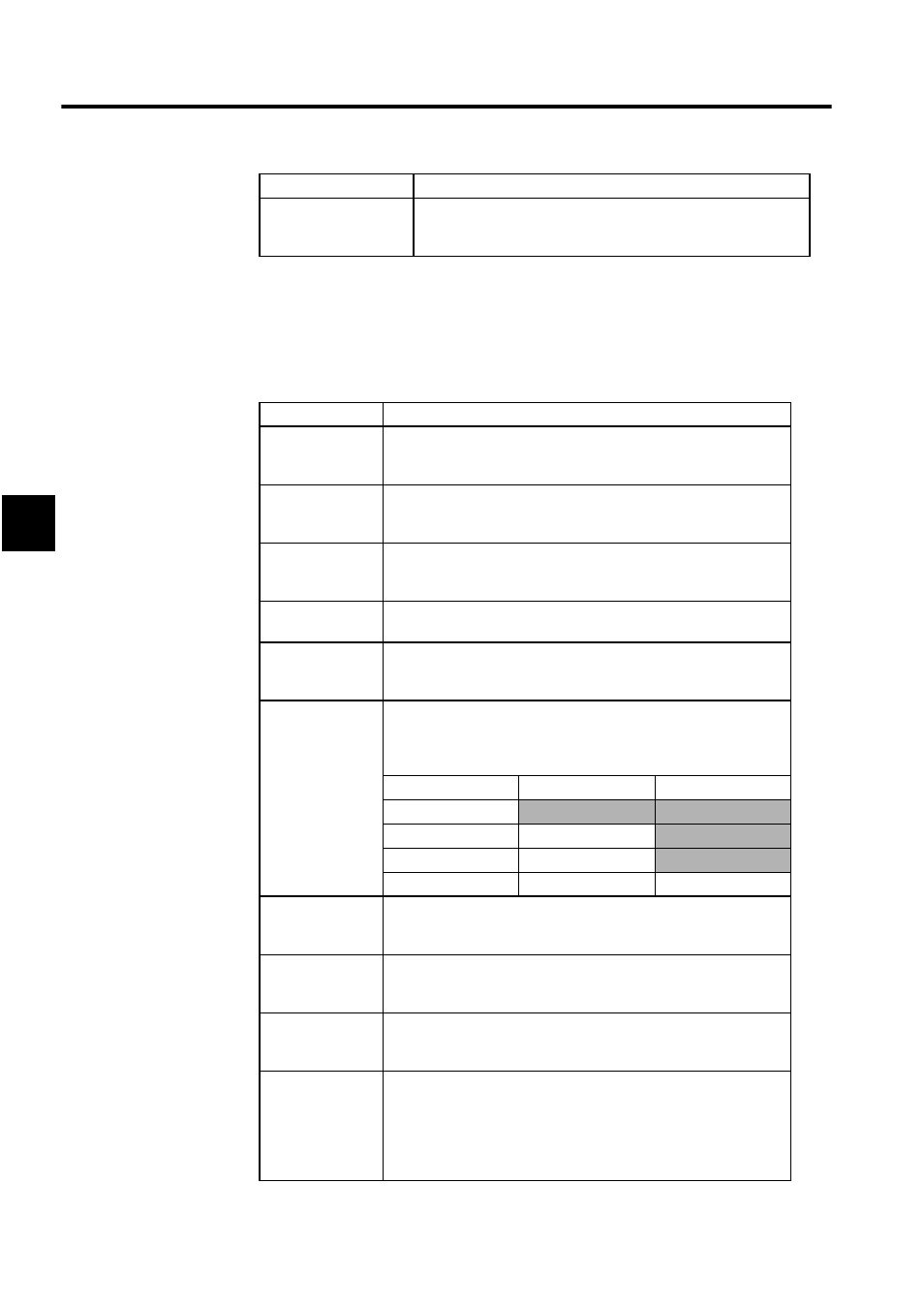
BSIZE
Displays in bytes the size of the input area (input register IWxxxx)
allocated to the relevant device. Specify from 1 to 256 (in decimal) for
1 slave. For example, if setting 3 bytes from IW1100 and 1 byte from
IW1102, the registers are used as shown below.
Register Address
F to 8
7 to 0
IW1100H
IW1101H
IW1102H
IW1103H
D
Output enable/disable sets whether or not the Controller CPU
exchanges I/O data with the 260IF. Select it to disable I/O data
exchange.
OUTPUT
Set the leading address of the output area (output register OWxxxx)
allocated to the relevant device. Specify using hexadecimal word
address.
BSIZE
Displays in bytes the size of the output area (output register OWxxxx)
allocated to the device. Specify from 1 to 256 (in decimal) for 1 slave.
The bytes are little endian, the same as the input registers.
SCAN
The data exchange cycle (SCAN) is the timing for exchanging I/O data
between the Controller CPU and the 260IF. The Controller CPU data
exchange cycle is asynchronous with I/O transmission. When set to
High, the Controller CPU exchanges I/O data using the CPU's high-
speed scan timing. When set to Low, the Controller CPU exchanges
data using the CPU's low-speed scan timing.
Setting Item
Details